49
Powerware 9315 (100 kVA--160 kVA) Installation
164200292 Rev. E 041500
Installing a Supervisory Contact
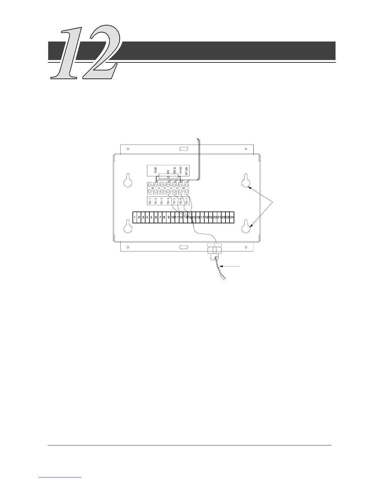
The optional Supervisory Contact Module (SCM) as shown in Figure
26 provides contacts for monitoring UPS status. A maximum of two monitoring
accessories (RMPs, RIMs, or SCMs) can be installed. Refer to Chapter 10, Table D
for the number of accessories permitted. See Drawing 164200292---12 in Appendix
A for enclosure dimensions, side views, and knockout patterns.
WIRES MUST
BE TWISTED
SURFACE MOUNT
(FOR HANGING)
Figure 26. Supervisory Contact Module
To install a Supervisory Contact Module:
1. Securely mount the SCM.
2. Install wiring from the SCM using ½-in. conduit through the 7/8-in. knockout in
either the top or bottom of the UPS cabinet.
The top entry connection requires installation of ½-in. flexible conduit within the
UPS. Bottom entry connection requires no additional routing of conduit within
the U PS.
3. If not already installed, locate the RMP adapter cable assembly (see Figure 27)
in the spare parts kit. Mate the DE---9 connector on the back of the terminal
block into the DE---9 connector on the Communications Panel of the UPS (see
Figure 28). Use two screws from the spare parts kit to s ecure the terminal
block bracket to the Communications Panel.



 To Next Page