1
Powerware 9315 (100 kVA--160 kVA) Installation
164200292 Rev. E 041500
Introduction
This manual describes how to install your Powerware
9315
Uninterruptible Power Supply (UPS) system. It contains instructions for
installing the UPS and each optional component and accessory. The information
you will use depends on the system you purchased.
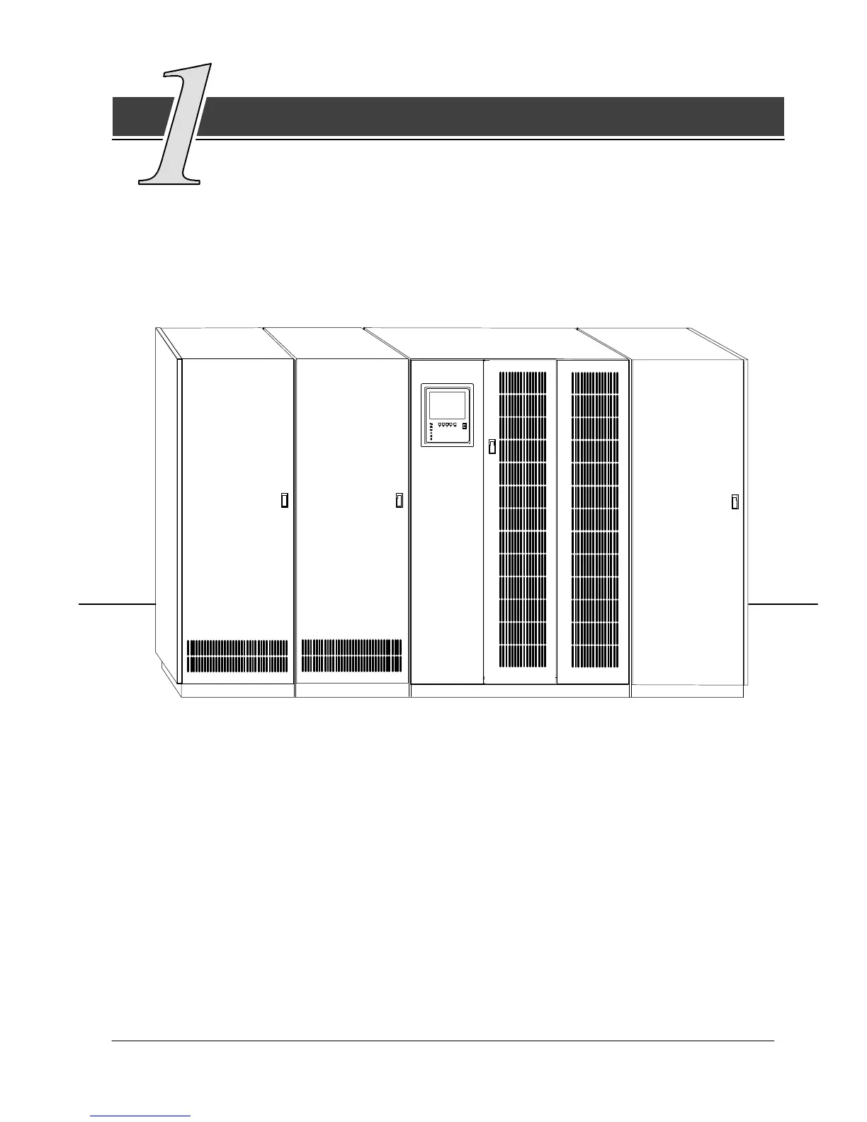
Each component of your UPS system is housed in a free-standing cabinet. The
cabinets line up and match in style and color, and have safety shields behind the
doors for hazardous voltage protection. Figure 1 shows a sample UPS system that
includes at least one of each component.
(optional)
PDM CABINET
(optional)
INPUT
TRANSFORMER
CABINET
CABINET
UPS
CABINET
BATTERY
(up to four)
Figure 1. Typical UPS System
These basic UPS system configurations are possible:
· The UPS and one or more battery cabinets
· The UPS, battery cabinet(s), and a Power Distribution Module (PDM)
· The UPS, battery cabinet(s), and an input transformer
· TheUPS,batterycabinet(s),PDM,andinputtransformer.
Yo u can enhance any of these system configurations by adding optional accessories,
such as a Remote Monitor Panel (RMP), Relay Interface Module (RIM),orRemote
Emergency Power Off (EPO) control.