35
Powerware 9315 (100 kVA--160 kVA) Installation
164200292 Rev. E 041500
Installing a Remote EPO Control
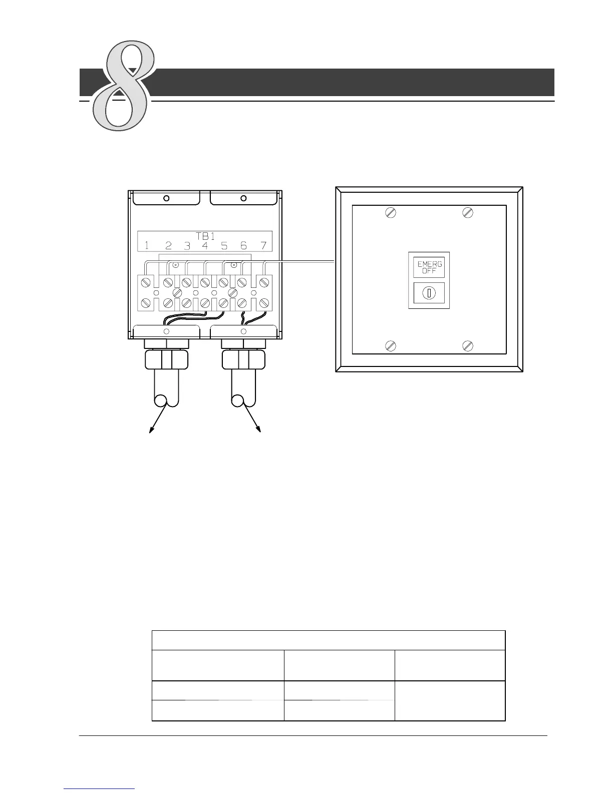
The Remote EPO control arrives as shown in Figure 18. See Drawing
164200292---9 in Appendix A for enclosure dimensions, side views, and
knockout patterns.
EMERGENCY OFF
UNINTERRUPTIBLE POWER SYSTEM
to UPS to other equipment
Figure 18. Remote EPO Control
To install a Remote EPO control:
1. Securely mount the Remote EPO station. Recommended locations include
operator’s consoles or exit doors.
2. Install wiring from the Remote EPO station using ½-in. conduit through the
cable entry panels in either the top or bottom of the UPS.
3. Connect the Remote EPO wiring as shown in Tables B and C:
TableB. RemoteEPOWireTerminations
From Remote
EPO Station(s)
To Communications
Panel in UPS
Remarks
T B 1 --- 4 T B 2 --- 1
Twisted wires
2
T B 1 --- 5 T B 2 --- 2
14---18 gauge



 To Next Page