Chapter 5 Function parameter
98
selection shall be set to 43 (PID parameter switching terminal), select parameter group 1 (E2.13
E2.15) when the terminal is inactive, otherwise select parameter group 2 (E2.16 to E2.18).
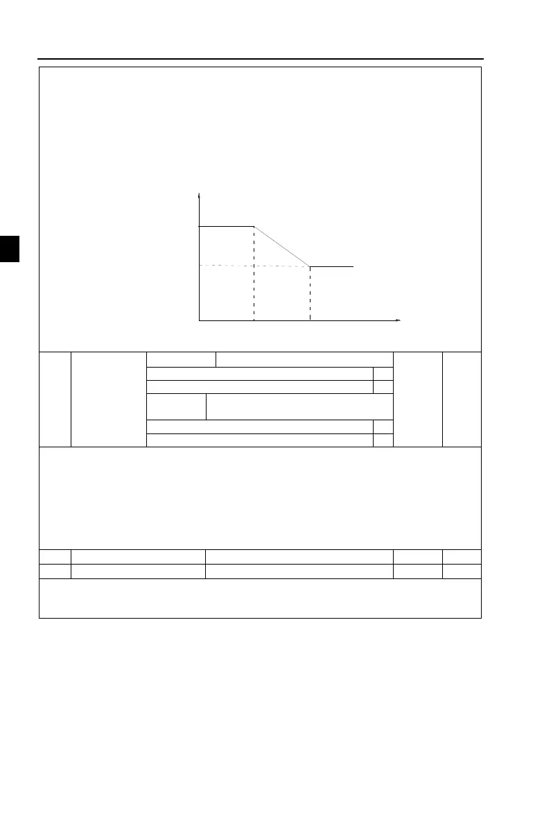
If you select the automatic switch mode, and when the absolute value of deviation between
reference and feedback parameters is less than PID parameter switching deviation 1(E2.20),
select parameter group 1 for PID parameter. When the absolute value of deviation between
reference and feedback parameters is more than PID parameter switching deviation 2(E2.21),
select parameter group 2 for PID parameter. If the deviation between reference and feedback
parameters is between switching deviation 1 and switching deviation 2, PID parameter is the
linear interpolation of the two groups of PID parameters , as shown in the figure.
PID parameter 1
E2.13、E2.14、E2.15
PID deviation
PID parameter
E2.20
E2.21
PID parameter 2
E2.16、E2.17、E2.18
Figure 5-32:PID parameter switching
Whether stop integration when output
reaches limit
Integral separation:If the integral separation is set to active, when the integral pause of
multifunction digital DI(Function 38) is active, PID integral will stop operations, at the time
only the proportional and derivative actions of PID is active.If the integral separation is set to
inactive, however the multifunction digital DI is active or inactive, the integral separation will
be inactive. Whether stop integration when output reaches limit: you can select whether or not
to stop the integral action after PID operation output reaches the maximum or the minimum
value If you select to stop the integral action, the PID integral will stop the calculation, which
may help to reduce the overshoot of PID.
PID initial value hold time
When the inverter starts, PID output is fixed at PID initial value(E2.23), and then
continuous for the PID initial value hold time(E2.24), at last PID begins operation of the
closed-loop adjustment.The figure is functional schematic of PID initial value.
 Loading...

