Chapter 5 Function parameter
65
0: unrepeatable Two different multi-function input terminals can not be set to the same
function.
1:Repeatable Two different multi-function input terminals can be set to the same function
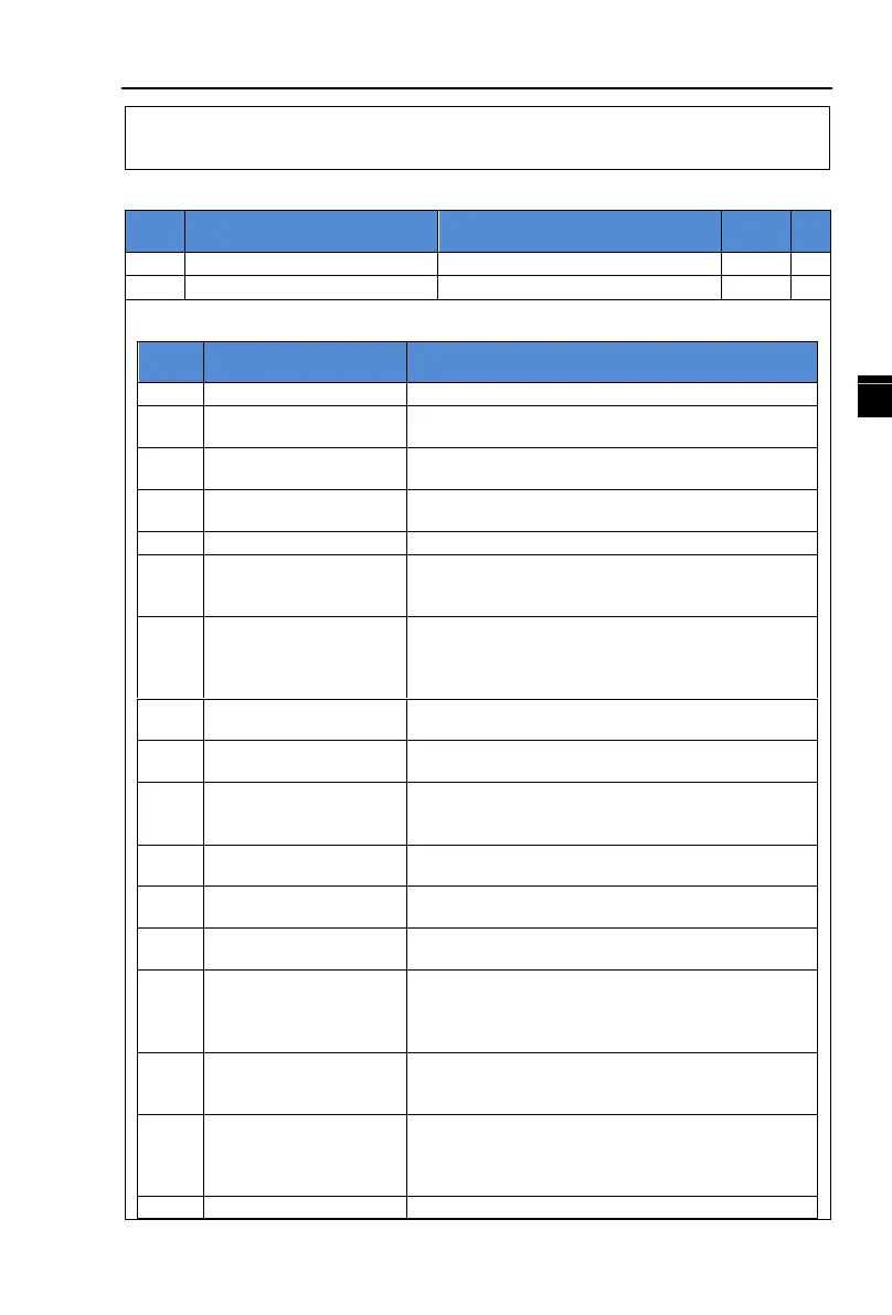
5-2-4.F2 group Output terminals group
Relay
output
function
selection
SPA output
function
selection
The above two function codes are used to select five digital output functions.
Multifunction output terminal function is described as follows:
The inverter is in operation with output frequency
(zero), and outputs ON signal
Fault output ( fault
shutdown)
When the inverter occurs failure and stops, and
outputs ON signal
Frequency level
detection FDT1 output
Please refer to the instructions of function code
F7.23,F7.24
Please refer to the instructions of function code 7.25
Zero speed running
(Shutdown without
output)
Outputs ON signal when the inverter is in operation
with output frequency(zero) Outputs OFF signal when
the inverter is in the sate of stop
Before motor overload protection action,it will output
ON signal if it exceeds the pre-alarm threshold. Please
refer to function code F8.02 to F8.04. for motor
overload parameter setting.
Inverter overload pre-
alarm
Outputs ON signal within 10s before inverter overload
protection action
Outputs ON signal when the count value
reaches the value set by E0.08.
Specified count value
arrival
Outputs ON signal when the count value
reaches the value set by E0.09. Please refer to the
instructions of E0 group for counting function.
Outputs ON signal when the detected,ctual length
exceeds the set length by E0.05.
Outputs a width of 250ms pulse signal when simple
PLC completes a cycle
Cumulative running time
arrival
Outputs ON signal when the inverter's cumulative
running time F6.07 exceeds the set time by F7.21.
Outputs ON signal when the rated frequency exceeds
the upper limit frequency or the lower limit frequency,
and the output frequency of inverter also reaches the
upper limit frequency or the lower limit frequency.
Outputs ON signal when the output torque reaches the
torque limit value and the inverter is in the stall
protection status under inverter speed control mode
Outputs ON signal when the power supply of the
inverter main circuit and control circuit has stabilized,
and the inverter has not any fault information and is in
the runnable status.
Outputs ON signal when the operating frequency
 Loading...

