Chapter 5 Function parameter
67
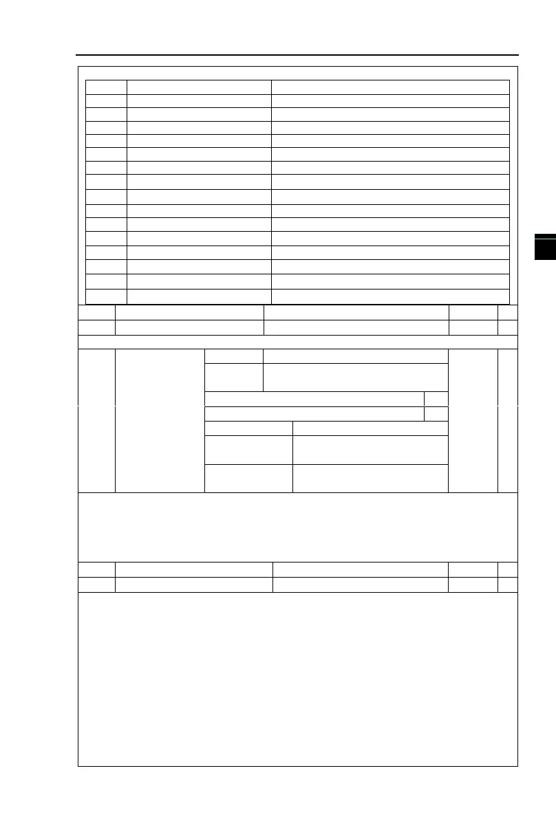
or analog output and the corresponding calibration relation are shown in the following table:
0 to maximum output frequency
0 to maximum output frequency
0 to 2 times rated motor current
0 to 2 times rated motor torque
0 to 1.2 times rated inverter voltage
0 to speed with maximum output frequency
Frequency source main set
Set the delay time from occurrence to Actual output for output terminal SPA and relay .
DO output
terminal active
status selection
Relay terminal active status
setting(0~1,as above)
SPA terminal active status
setting(0~1,as above)
To define the output logic for output terminal SPA and Relay
0: Positive logic:It is active status when the digital output terminal is connected with the
corresponding common terminal, inactive when disconnected;
1: Anti-logic:It is inactive status when the digital output terminal is connected with the
corresponding common terminal, active when disconnected;
DA1 zero bias coefficient
The above function codes are generally used for correcting the zero drift of analog output
and the deviation of output amplitude. It also be used to custom analog output curve.
Take DAI as an example , calculation formula as follows:
y1 refers to the minimum output voltage value or current value of DA1; y2 refers to the
maximum output voltage value or current value:y1=10V or 20mA*F2.16*100%;
y2=10V or 20mA*(F2.16+F2.17);
Factory default F2.16=0.0%, F2.17=1, so the output 0~10v (or 0~ 20mA) is coreesponding
to the minimum value to the maximum value of characterization of pahsical quantities.
Example 1:
Change the output 0~20mA to 4~20mA
According to the formula, minimum input current value:y1=20mA*F2.16*100%,
4=20*F2.16, work out F2.16=20%;
According to the formula , maximum input current value :y2=20mA*(F2.16+F2.17);
 Loading...

