Operation
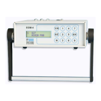
EGM-4 Operator's Manual – Version 4.19
- 41 -
• If an RH sensor is fitted, a
reading above 90% could
mean condensation.
(see PP Systems’
Contact Information
• Battery voltage < 10.5v
EGM Serial Outputs
(For Use With WINDOWS Data Transfer Program or other terminal program)
The following data strings are output from the EGM-4 with no user intervention.
On Starting:
<SP>B, EGM4,Serial Number, Firmware version<CR>
<SP>=Space, <CR>=Carriage return.
Then during the delay period at the start:
<SP>I, NN <CR>
Where NN is the same as the count on the EGM display.
During Warm up
<SP>W,TT<CR>
Where TT is the cell temperature.
During ZERO
<SP>Z,NN<CR>
Where NN is the same as the EGM display count.
During Diagnostics a data string is transmitted through the RS232:
<SP>D,ZZZZZ,CCCCC,ANLT,HHHH,HTHT,INPB,INPC,INPD,INPE,ATMP<CR>.
(These values are the reads from the A/D converters and have not been scaled.)
Where:
Stored Analyzer reading during last zero.
Analyzer temperature sensor reading.
Reading of the internal humidity sensor (optional).
Reading from the temperature sensor (optional).
Corresponds to the mV inputs from external sensors (A-E).
Reading from the pressure transducer (mb).
5CLR
To clear data stored in memory, press key 5.
(YY-N)?