COMMERCIAL
PRO
D U C T S
DIVISION
Diagram 7
Diagram 8
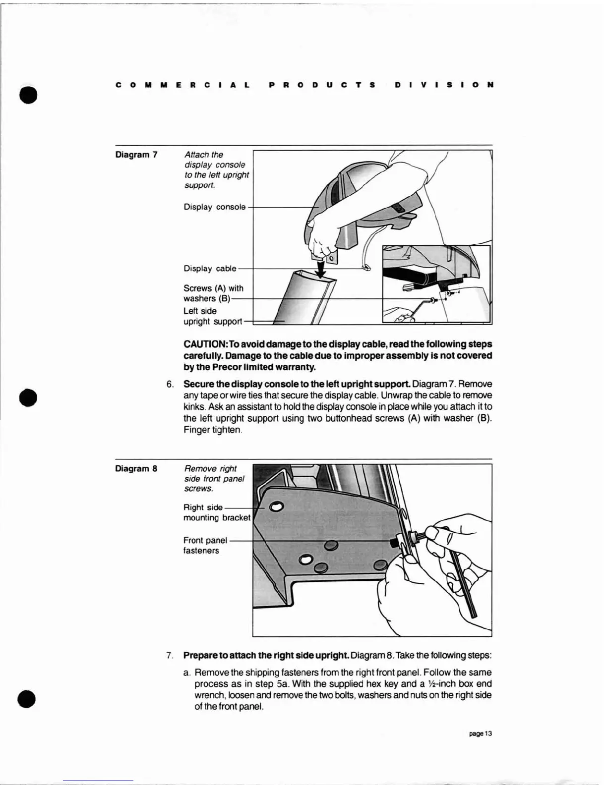
Attach the
display console
to the left upright
support.
Display console
-+-----_+_
Display
cable--r--.~~~------,,~
Screws (A)
with
washers (8)
---t-----fr----,j1-f-----f------::="OO
Left side
upright support
-t==£=-_----lu.
.!::::~~==~===::::!1
CAUTION:
To
avoid damage to the display cable, read the following steps
carefully. Damage to the cable due to improper assembly is not covered
by
the Precor limited warranty.
6.
Secure the display console
to
the left uprightsupport. Diagram
7.
Remove
any tape or wire ties that secure the display cable. Unwrap the cable to remove
kinks. Ask
an
assistant to hold the display console
in
place while you attach it to
the left upright support using two buttonhead screws (A) with washer (B).
Finger tighten.
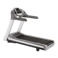
Remove right
side front panel
screws.
Right
side
--
~
mounting bracket
Front
panel--i-''t----~~
__
----
..
.:
fasteners
7.
Prepare
to
attach the right side upright. Diagram 8.
Take
the following steps:
a.
Remove the shipping fasteners from the right front panel. Follow the same
process as in step 5a. With the supplied hex key and a
Y2-inch
box end
wrench, loosen and remove the two bolts, washers and nuts on the right side
of the front panel.
page 13