---------------------------
COMMERCIAL
PRO
D U C T S
DIVISION
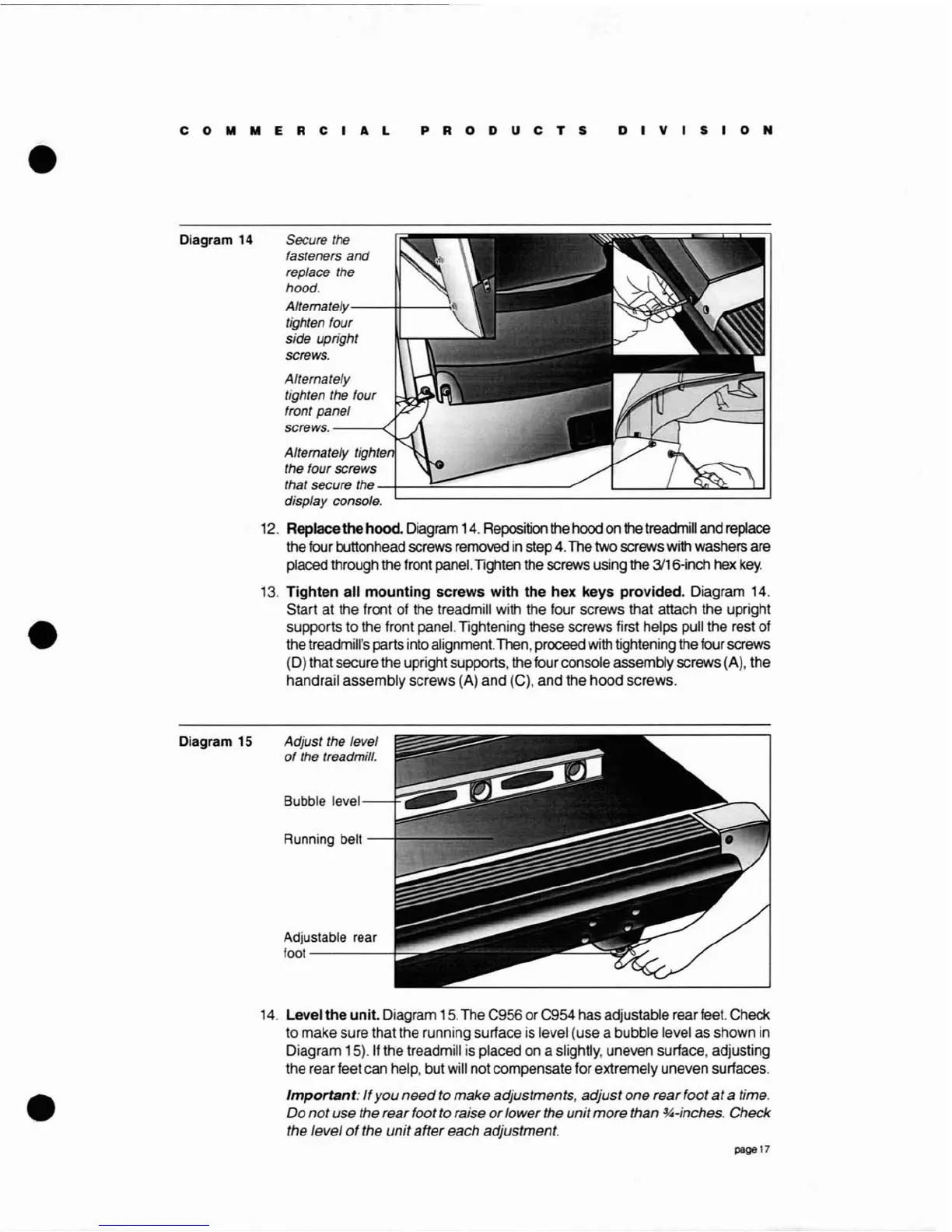
Diagram 14
Diagram 15
Secure
the
fasteners and
replace the
hood.
Altemately---++----i"
tighten four
side upright
screws.
Alternately
tighten the four
front panel
screws.
---<.
Alternately tighte
the four screws
that secure the
-11------':::....---------"
display console.
12.
Replace
the
hood.
Diagram
14.
Reposition
the
hood
on
the
treadmill
and
replace
the
four
buttonhead screws
removed
in
step
4.
The
two screws
with
washers are
placed through
the
front
panel.
Tighten
the
screws using
the
3116-inch
hex
key.
13.
Tighten all mounting screws with the hex keys provided. Diagram
14.
Start
at
the
front
of
the
treadmill
with
the four screws that attach the upright
supports to
the
front panel. Tightening these screws first helps
pull
the rest
of
the
treadmill's parts
into
alignment.
Then,
proceed
with
tightening
the
four
screws
(D)
that secure
the
upright supports,
the
four console assembly screws (A), the
handrail assembly screws
(A) and (C), and the hood screws.
Adjust the level
of
the treadmill.
Bubble
level---+-,.
Running
belt
--+~
Adjustable rear
foot
-----+-::
14.
Level the unit. Diagram
15.
The
C956 or C954 has adjustable rear
feet.
Check
to
make sure that the running surface
is
level (use a bubble level
as
shown
in
Diagram 15).lf the treadmill
is
placed
on
a slightly, uneven surface, adjusting
the
rear feet can help, but
will
not compensate for extremely uneven surfaces.
Important:
If
you
need
to
make
adjustments,
adjust
one
rear
foot
at
a time.
Do
not
use the rearfoot to raise
or
lower
the
unit
more
than
~-inches.
Check
the
level
of
the
unit
after
each adjustment.
page 17