COMMERCIAL
PRO
D U C T S
DIVISION
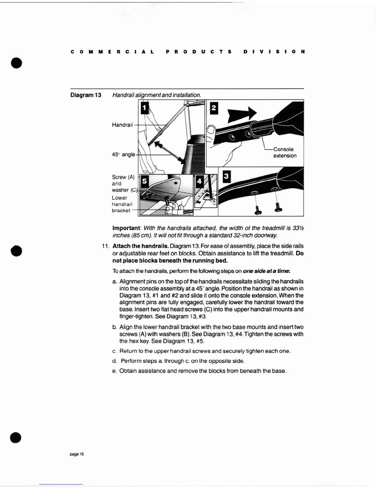
Diagram
13 Handrailalignment
and
installation.
Handrail-+-+---'-<:T--T/
45°
angle
-ffi-+-Ir------:!I.
Screw
(A)
and
washer
(C
Lower
handrail
bracket
-+h"L-7"4c~'-P--bJ=:J'---'1
Important:
With the handrails attached, the width
of
the treadmill is
33M!
inches (85 cm). It will
not
fit through a standard32-inch doorway.
11.
Attach
the
handrails.
Diagram 13. For ease of assembly, place the side rails
or adjustable rear feet on blocks. Obtain assistance to lift the treadmill.
Do
not
place
blocks
beneath
the
running
bed.
To
attach the handrails, perform the following steps on
one
side
at
a time:
a.
Alignment pins on the top of the handrails necessitate sliding the handrails
into the console assembly at a
45°
angle. Position the handrail as shown
in
Diagram 13,
#1
and #2 and slide it onto the console extension. When the
alignment pins are fully engaged, carefully lower the handrail toward the
base. Insert two flat head screws (C) into the upper handrail mounts and
finger-tighten. See Diagram 13, #3.
b.
Align the lower handrail bracket with the two base mounts and insert two
screws (A) with washers (B). See Diagram 13, #4. Tighten the screws with
the hex
key.
See Diagram 13, #5.
c. Return to the upper handrail screws and securely tighten each one.
d.
Perform steps
a.
through
c.
on the opposite side.
e.
Obtain assistance and remove the blocks from beneath the base.
page
16