APSRS_RevC_9/19
2
Detailed Descripons: Wire Harness Colors and Funcons
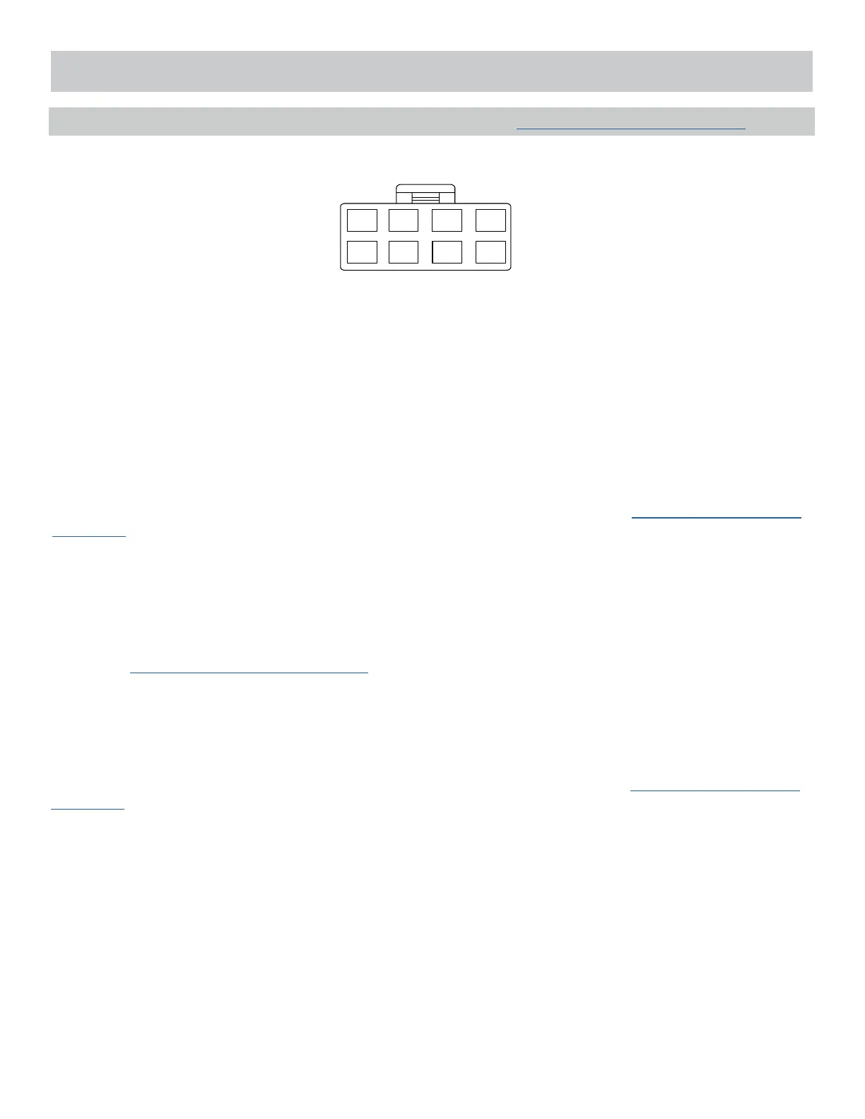
Power Connector (8-pin High-Current Connector) See page 28 for the full system diagram.
These wires are listed in order of their placement in the harness connector.
3. YELLOW – Starter Output for Remote Start (+)
The YELLOW wire supplies 12-Volt (+) to the vehicle’s starter wire when remote start is enabled, and turns o once the
vehicle is started.
Vericaon: This starter wire registers 12-Volt (+) during engine crank.
Note: If installing a starter kill relay in addion to remote start, connect the YELLOW wire to the MOTOR SIDE of the cut
starter wire. Refer to Start Kill diagram on page 29.
5. RED – 12-Volt Input (+)
The RED wire connects to the vehicle’s primary 12-Volt (+) wire to power the system.
Vericaon: The power wire registers 12-Volt (+) at all mes.
Note: Before making this connecon, remove all module fuses unl the system is completely connected.
4. GREEN – Ignion 2 Output (+)
At its default seng, the GREEN wire supplies 12-Volt (+) to the vehicle’s secondary ignion wire during remote start.
Vericaon: If present, the secondary ignion wire registers 12-Volt (+) when the vehicle is in ignion mode AND during
engine crank.
Note: This wire can be programmed to perform a dierent funcon by changing its opons. Refer to Bank 3, Feature 7
on page 12.
6. RED/WHITE – 12-Volt Input (+)
The RED/WHITE wire connects to the vehicle’s secondary 12-Volt (+) wire to power the remote start funcon.
Vericaon: The power wire registers 12-Volt (+) at all mes.
Note: Before making this connecon, remove all module fuses unl the system is completely connected.
1 3 5 7
2 4 6 8
1. RED/BLACK – Ignion 3, Flex Relay Input (Internal Relay Pin 87)
The RED/BLACK wire is used to supply the Pin 2 - PINK Flex Relay Output. This wire can be connected to 12-Volt (+) or
Ground (-). Please check vehicle requirements for correct polarity.
Note: Before making this connecon, remove all module fuses unl the system is completely connected.
2. PINK – Ignion 3 Flex Relay Output (Internal Relay Pin 30)
At its default seng, the PINK wire supplies 12-Volt (+) or Ground (-) to the vehicle’s secondary ignion wire during
remote start. The polarity of this output is provided by the Pin 1, RED/BLACK Input.
Vericaon: If present, the secondary ignion wire registers 12-Volt (+) or Ground (-) when the vehicle is in ignion mode
AND during engine crank.
Note: This wire can be programmed to perform a dierent funcon by changing its opons. Refer to Bank 3, Feature 8
on page 12.