APSRS_RevC_9/17
3
Detailed Descripons: Wire Harness Colors and Funcons
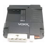
Nocaon Connector (4-pin connector) See page 28 for the full system diagram.
These wires are listed in order of their placement in the harness connector.
2. WHITE/RED – Parking Light Relay Input (Internal Relay Pin 87)
The WHITE/RED connects to vehicle 12-Volt (+) or Ground (-) to supply the relay output (WHITE wire).
Vericaon for default seng:
• If the vehicle parking light wire registers 12-Volt (+) when the park lights are on, connect the WHITE/RED wire to a
constant 12-Volt (+) vehicle wire.
• If the vehicle parking light wire registers Ground (-) when the park lights are on, connect the WHITE/RED wire to a
reliable vehicle ground source.
Note: This wire can be programmed to perform the Trunk Release Output funcon by changing its opons. Refer to
Bank 2, Feature 14 on page 9.
1. WHITE – Parking Light Relay Output (Internal Relay Pin 30)
At its default seng, the WHITE wire supplies 12-Volt (+) or Ground (-) to the vehicle's park light wire based on the
connecon of the relay input (WHITE/RED wire).
Vericaon: The vehicle parking light wire registers 12-Volt (+) or Ground (-) when the park lights are turned on.
Note: This wire can be programmed to perform the Trunk Release Output funcon by changing its opons. Refer to
Bank 2, Feature 14 on page 9.
4. BLACK – Ground Input (-)
The BLACK wire connects to a reliable vehicle ground (-) source to power the system.
Vericaon: The vehicle ground (-) source wire registers ground (-) at all mes.
Note: Before making this connecon, remove all module fuses unl the system is completely connected.
1 3
2 4
8. BLUE – Ignion 1 Input / Output (+)
The BLUE wire supplies 12-Volt (+) to the vehicle’s primary ignion wire during remote start. This wire is also used to
sense vehicle ignion for the Programming Funcons
Vericaon: The primary ignion wire registers 12-Volt (+) when the vehicle is in ignion mode AND during engine crank.
7. PURPLE – Accessory Output (+)
At its default seng, the PURPLE wire supplies 12-Volt (+) to the vehicle’s accessory wire to power vehicle accessories
during remote start.
Vericaon: The accessory wire registers 12-Volt (+) when the vehicle is running or in accessory mode, but not during
engine crank or if the vehicle is o.
Note: This wire can be programmed to perform a dierent funcon by changing its opons. Refer to Bank 3, Feature 9
on page 12.
Power Connector (8-pin High-Current Connector) (Cont) See page 28 for the full system diagram.
These wires are listed in order of their placement in the harness connector.
3. YELLOW/BLACK – Ignion Output to Alarm (+)
The YELLOW/BLACK wire supplies 12-Volt (+) ignion output when the vehicle's ignion is set to ON, but not during the
remote start runme. This output will be used when an external alarm system is added to the vehicle.