APSRS_RevC_9/19
4
Detailed Descripons: Wire Harness Colors and Funcons
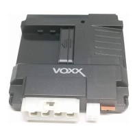
Input / Output Connector (22-pin connector) See page 28 for the full system diagram.
These wires are listed in order of their placement in the harness connector.
9. BLACK/YELLOW – Pulse During Crank Output (-) (NOC 3)
At its default seng, the BLACK/YELLOW wire supplies a Ground (-) pulse when the engine cranks during remote start.
Note: This wire is programmable. Refer to NOC Programming on page 16
21
22
19
20
17
18
15
16
13
14
11
12
9
10
7
8
5
6
3
4
1
2
1. ORANGE – Starter Kill Output (-)
The ORANGE wire supplies Ground (-) when the alarm is armed and when the remote start is ON.
2. LIGHT GREEN – Trunk / Hatch Input (-)
The LIGHT GREEN wire connects a device or switch that, when triggered, supplies a Ground (-) output. If the system is
armed, this input will trigger the alarm.
3. GRAY/BLACK – Hood Input (-)
The GRAY/BLACK wire connects to the vehicle's hood switch, or an installed switch that registers Ground (-) when
triggered.
Vericaon: The vehicle hood switch wire registers Ground (-) when the hood is opened.
4. GREEN/ORANGE – Tach Input
The GREEN/ORANGE wire connects to the vehicle’s tach wire at the negave side of the ignion coil or fuel injector to
control engine crank during remote start.
Vericaon:
• Using a voltmeter set to AC volts, connect the voltmeter’s posive lead to a constant vehicle
12-Volts (+) source and the negave lead to the wire to be tested.
• Start the engine and have a partner slowly press the gas pedal while the transmission is in Park. If the voltage
increases as the RPM increases, this is the proper tach wire.
5. LIGHT BLUE – Remote Start Status Output (-) (NOC 1)
The LIGHT BLUE wire supplies Ground (-) as soon as the remote starter is acvated and remains acve unl 4 seconds
aer remote start run me has ended. This wire is most commonly used to acvate data integraon modules.
Note: This wire is programmable. Refer to NOC Programming on page 16.
6. PURPLE/BROWN – Door Trigger Input (-/+)
The PURPLE/BROWN wire connects to the vehicle's door trigger wire. This wire will detect 12-Volt (+) or Ground (-) input.
Vericaon: The vehicle door trigger wire registers 12-Volt (+) or Ground (-) when a door is opened and opposite when
closed.
Note: Programming is required if the door trigger wire registers 12-Volt (+). Refer to Feature Programming on page 9.
7. GREEN/WHITE – Dome Light Output (-) (NOC 2)
The GREEN/WHITE wire supplies Ground (-) when Unlock is acvated from the Remote Control. This output will
automacally turn o aer 30 seconds.
Note: This wire is programmable. Refer to NOC Programming on page 16.
8. GREEN/YELLOW – Diesel Glow Plug Input (+)
The GREEN/YELLOW wire connect to the vehicle's Diesel Glow Plug detecon wire.
Vericaon: This wire will register as 12-Volt (+) while the Diesel Wait to Start Light is illuminated.