Alternator
Battery indicator light is mounted
on
the
instrume~t
panel in front
of
the driver to signal when alternator
1s
not
chargi11g
. When this
occurs
under
normal ope-
rating conditions, vehicle should be driven only as far
as necessary to reach a point
of
safety.
Engine alarm system
Engine is equipped with
an
alarm system to indi
ca_te
low oil pressure and
high
engine temperature.
1COrln
and uhot water» indicators are located
on
the instru-
ment panel
in
front
of
the driver. In addition. an alarm
buzzer sounds when either condition occurs.
The automatic shut-down device, operating through a
time delay safety control relay interconnected with the
alarm system, will stop the engine when
one
of
these
abnormal conditions
occurs
.
Stopping engine
1. Apply parking brake and make sure that transmis-
sion shift lever is placed in neutral position. This will
ensure that the transmission neutral start safety swit-
ches are closed and witl allow future restarting of the
engine.
2. Wait
30
seconds, allowing engine to idle, then turn
ignition key to uoff
11
position. This will activate control
shut-off mechanism and stop engine.
•
WARNING:
If i
gn
iti
on
sw
itch does not stop engine,
or
in case of an emergency, push
on
engine
emer
-
gency
stop switch. This will release an
air
choke
v~lve
cam
and stop engine. Engine emergency stop switch
should be returned to its original position after engine
has stopped by releasing the switch. This warning does
not apply to vehicles equipped with a turbocharged
engine.
Engine emergency stop
When engine
does
not stop after ignition key switch
has been turned to off position
or
when it gets out
of
control it can be stopped through use of the «engine
emergency stopu switch located
on
front switch panel.
This engine emergency stop system is not required
on
turbocharged engine.
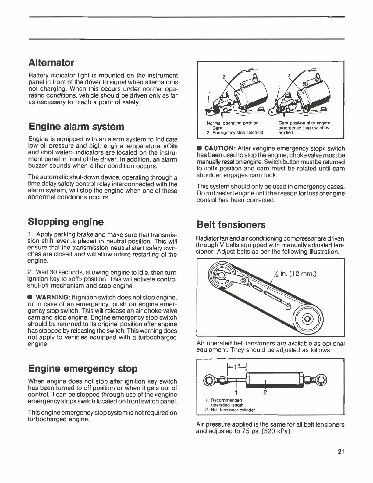
Normal operat ng position
t
Cam
2 Emergency stop solen
0o
d
Cam
pos1t1on
alter engine
emergency stop switch
1s
applied
•
CAUTION:
After uengine emergency stopn switch
has been used to stop the engine, choke valve must
be
manually
reset
on engine. Switch button must be returned
to «offn position and
cam
must
be
rotated until
cam
shoulder engages
cam
lock.
This system should only be used in emergency
cas~s.
Do
not restart engine until the reason for loss
of
engine
control has been corrected.
Belt tensioners
Radiator fan and air conditioning compressor are driven
through V-belts equipped with
manu~lly
~djusle~
ten-
sioner. Adjust belts as per the following
1llustrat1on.
Air operated belt tensioners are available as optional
equipment. They should be adjusted as follows:
1 2
I Recommended
operating
length
2. Belt tensroner cylinder.
Air pressure applied is the same for all belt tensioners
and adjusted to 75 psi
(520
kPa).
21