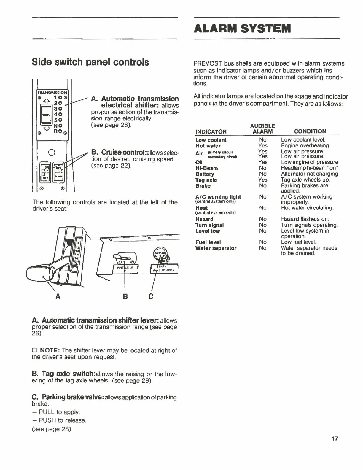
Side
switch
panel
controls
TRANSMISSION
®S~~e
;~
NO
0
R0
9
A.
Automatic
transmission
electrical
shifter:
aHows
proper selection of the transmis-
sion range electrically
(see page 26).
B.
Cruise
control:allows selec-
tion of desired cruising speed
(see page 22).
The following controls are located at the left of the
dr
iver's seat:
A B c
A.
Automatic
transmission
shifter
lever:
allows
proper serec
ti
on of the transmission range (see page
26
).
D NOTE: The shifter lever may be located at right of
the driver's seat upon request.
B.
Tag
axle
switch:a
llows the raising
or
the l
ow
-
ering of the
tag
ax
te wheels. (see page 29).
C.
Parking
brake
valve:
allows application or parking
brake.
- PULL to apply.
-
PUSH to release.
(see page 28).
ALARM
SYSTEM
PREVOST bus shells are equipped with alarm systems
sucn as indicator lamps
and/or
buzzers which ins
inform the driver of cenain abnormal operating condi·
lions.
All indicator lamps are located on the ugage and indicator
panel»
1n
the drivers compartment. They are
as
follows:
AUDIBLE
INDICATOR ALARM
CONDITION
Low coolant
No
Low coolant level.
Hot
waler
Yes
Engine overheating.
Air
Pfl-ry
cln:ult
Yes
Low air pressure_
HCOndary circuit Yes
Low air pressure_
011
Yes
Low engine oil pressure.
Hl·Beam
No
Headlamp hi-beam
"'
on
".
Battery
No
Alternator not charging.
Tag
axle
Yes
Tag
axle wheels up.
Brake
No
Parking brakes are
applied.
A/C
wamlng
ll~hl
No
A/C
system working
(central
system
0
11ty>
improperly_
Heat
No
Hot water circulating .
(cenlral
syslem
o
rll
y>
J
Hazard
No
Hazard
llashers
on
_
Turn
signal No
Turn signals operating.
Level
low
No Level low system in
operation.
Fuel level
No
Low fuel level.
Waler
separator
No
Water separator needs
to
be
drained.
17