HEATING
&
AIR
CONDITIONING
Two
(2)
different heating
and
air conditioning systems
are available in
«PREVOST11
bus shells. The standard
system is designed
for
the driver's
compartment
only.
The optional system
includes a central system in addi-
tion to the driver's heating and
A/C
system.
Driver's compartment heating
and
A/C
system
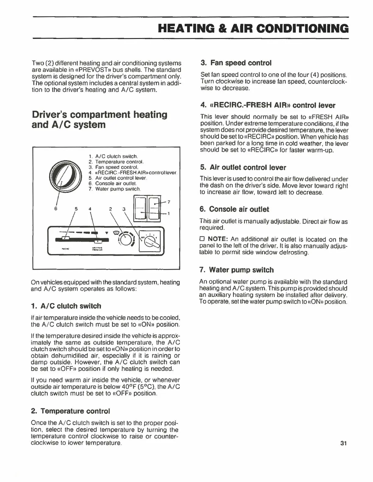
6
1.
A/C
clutch switch.
2. Temperature control.
3.
Fan
speed control.
4
uRECIRC -FRESH AIR11controllever
5 Air outlet control lever.
6 Console
air outlet.
7. Water
pump
switch.
On vehicles equipped with the standard system, heating
and
A/C
system operates
as
follows:
1.
A/C
clutch switch
U
air
temperature inside the vehicle needs to be cooled.
the
A/ C clutch switch
must
be set to
110N11
position.
If
the temperature desired inside the vehicle is approx-
imately
the same as outside temperature, the
A/C
clutch switch should be set to
uON11
position in
order
to
obtain dehumidified air, especially if it is raining
or
damp
outside. However, the A/ C clutch switch can
be set to
uOFF11
position if only heating is needed.
If
you need
warm
air inside the vehicle,
or
whenever
outside
air
temperature is below
40°F
(5°C)
, the
A/C
clutch switch
must
be set to ((OFF» position.
2. Temperature control
Once the A / C clutch switch is set to the
proper
posi-
tion. select the desired temperature
by
turning the
temperature control clockwise to raise
or
counter-
clockwise to
lower
temperature.
3. Fan speed control
Set fan speed control to
one
of
the
four
(4)
positions.
Turn clockwise to increase fan speed. counterclock-
wise to decrease.
4. uRECIRC.-FRESH AIRn control lever
This lever should normally be set to
11FRESH
AIR11
position.
Under
extreme temperature conditions, if the
system does
not
provide desired temperature, the lever
should be set to
«RECIRCn position. When vehicle has
been parked
for
a long time in cold weather, the lever
should
be
set to
11RECIRC11
for faster warm-up.
5. Air outlet control lever
This lever is used to control the air flow delivered
under
the dash
on
the driver's side. Move lever toward right
to increase air flow, toward left to decrease.
6. Console air outlet
This
air
outlet is manually adjustable. Direct
air
flow as
required.
D
NOTE:
An additional air outlet is located
on
the
panel to the left
of
the driver. It is also manually adjus-
table to permit side
window
defrosting.
7. Water pump switch
An optional water
pump
is available with the standard
heating
and
A/C
system. This
pump
is provided should
an auxiliary heating system
be installed after delivery.
To operate, set the water
pump
switch to uON u position.
31