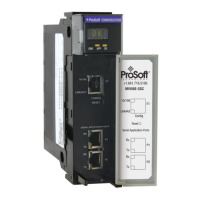
Reference MVI56E-GSC/GSCXT ♦ CompactLogix or MicroLogix Platform
User Manual Enhanced Generic ASCII Serial Communication Module
Page 74 of 140 ProSoft Technology, Inc.
April 24, 2017
CIPconnect
®
-enabled network diagnostics and monitoring using ControlLogix
1756-ENxT modules and EtherNet/IP
®
pass-thru communications
Sample Ladder Logic or Add-On Instruction (AOI) used for data transfers
between module and processor and for module configuration
4-character, scrolling, alphanumeric LED display of status and diagnostic
data in plain English
ProSoft Discovery Service (PDS) software finds the module on the network
and assigns a temporary IP address to facilitate module access
4.1.2 Functional Specifications
The MVI56E-GSC and MVI56E-GSCXT are functionally identical. The
MVI56E-GSC is for normal process and control environments. The MVI56E-
GSCXT is conformal coated for extra protection in harsh or caustic
environments and operates in extreme high or low temperature
environments.
Both modules transfer data in the largest possible I/O image block sizes,
which optimizes data through-put and update time.
Both modules appear to the ControlLogix processor as input/output (I/O)
modules, rather than communication modules.
Two ASCII serial communication ports:
o Can independently transmit and/or receive ASCII character strings and
serial byte streams
o Each port is individually configurable
Receive ASCII character strings or byte streams up to 4096 characters in
length
Received packet termination types:
o Stream mode (no packet termination)
o Receipt of specified character or characters
o Message length timeout
o Intercharacter spacing timeout
o Packet size limit (number of received characters/bytes)
Module configuration and communication configuration data is transferred to
the module via predefined sample ladder logic
Module error and status conditions returned to processor for diagnostic
purposes
o Module status
o Port error status word (bit mapped)
o Port receive state
o Port receive character count
o Port receive block count
o Port transmit state
o Port transmit character count
o Port transmit block count