93-331-73 Issue 2 Page 10 of 32 © Protec Fire Detection PLC 2013
7.0 Detector Circuit Connections
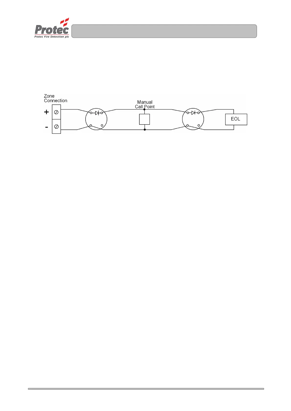
Figure 7 shows a typical connection regime for a detector zone on the 3200.
Figure 7.0 Typical 3200 Detector Connection
• Ensure the length of the zone wiring is no more than 500 metres.
• Ensure the resistance of each conductor is no more than 15Ω.
• Ensure the capacitance of the zone wiring is no more than 0.27µF (micro-Farads)
when no end of line capacitor is present.
• The end of line unit (8.2kΩ resistor or 100µF/22Ω network) must be placed at the very end of the
detector zone wiring, to ensure the whole zone is monitored.
• Spurs should not be connected from the zone wiring, as a spur cannot be monitored for open
circuit faults.
• To ensure compliance with EN54 Part 2 each detector base must include a series low voltage
drop diode, so that manual call points following a removed detector still function correctly. Protec
S3000 bases incorporate the diode as standard.
• Manual call points must incorporate a series resistor to ensure the zone does not enter a short
circuit fault condition when the manual call point is activated. If the panel is to be able to
distinguish between automatic and manual zone activation. The resistor value in the manual call
point must be 180Ω. In retrofit situations, values up to 560Ω can be used but the ‘MCP Fire’
indication may not be given in all cases.
Protec 3100 manual call points incorporate the series resistor as standard.
www.acornfiresecurity.com
www.acornfiresecurity.com