93-331-73 Issue 2 Page 11 of 32 © Protec Fire Detection PLC 2013
8.0 Alarm Circuit Connections
The 3200 has two alarm circuit outputs, rated for continuous use at 150mA and protected from over-
load by an auto resetting thermal ‘fuse’. The ‘fuse’ will reset when the cause of overload has been
removed and the alarm output has been de-activated.
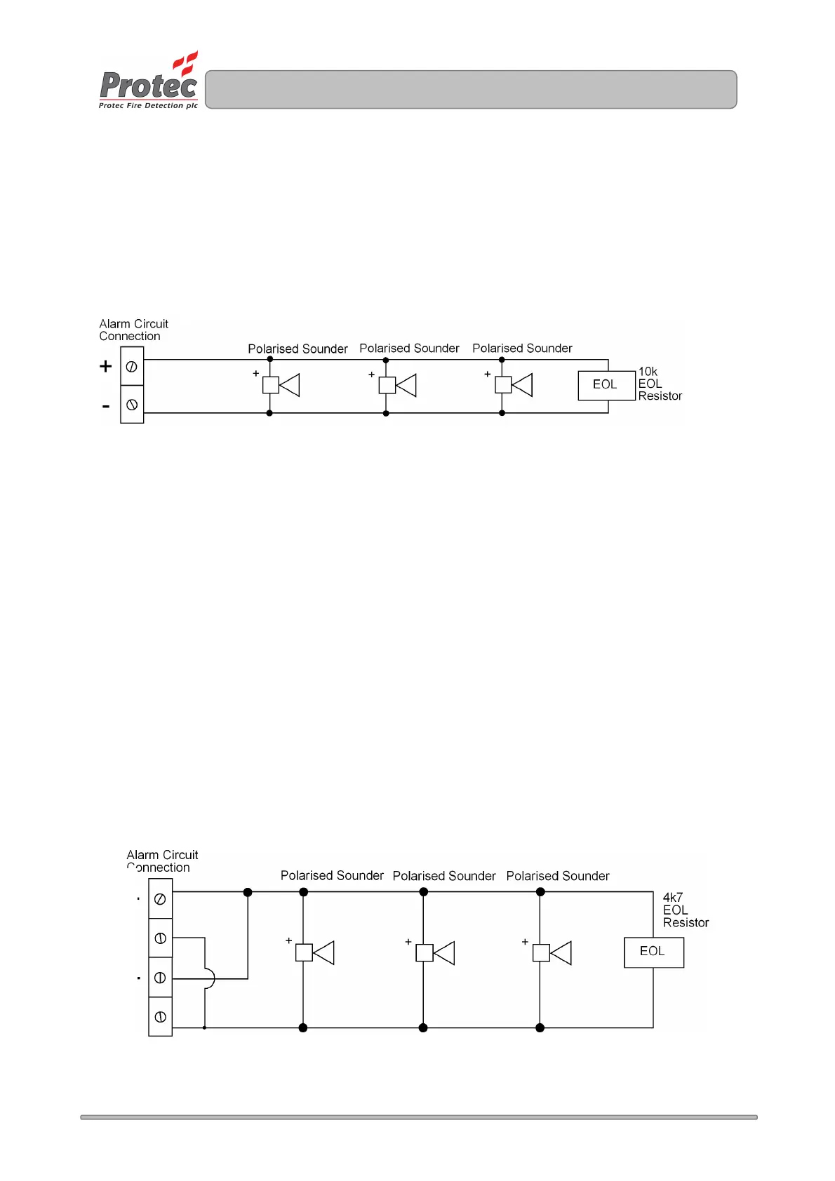
Figure 8 shows typical connections for a alarm circuit.
Figure 8.0 Typical Alarm Circuit Connection.
• Ensure the length of the alarm circuit wiring is no more than 500 metres.
• Ensure the capacitance of the alarm circuit wiring is no more than 0.27µF (micro-Farads).
• The 10kΩ end of line resistor must be connected at the very end of the alarm circuit wiring, to
ensure the whole line is monitored for open circuit faults.
• Spurs should not be connected from the alarm wiring, as the spur cannot be monitored for open
circuit faults.
• Only polarised and suppressed sounders should be used on the 3200 alarm circuits. Failure to
use polarised sounders will result in an alarm circuit fault. All Protec S3000 sounders are polarised
and suppressed as standard.
• Efforts should be made to evenly spread the sounder load across the two alarm circuits, to avoid
overloading either of the alarm outputs.
• It is acceptable to connect alarm circuits 1 and 2 in parallel (to obtain a drive rating of 300mA
continuous), however the end of line resistor value must be changed to 4k7Ω 1/2W 5%. This is
detailed in figure 8.1
Figure 8.1 Enhanced Alarm Circuit Drive Details
1
2
www.acornfiresecurity.com
www.acornfiresecurity.com