Installation
Remote Keypad Installation
Open the Remote keypad by removing the four stainless steel button head machine screws
on the sides of the keypad case. The front and back half will now separate. Mount the back
plate to the desired keypad location using the three keyed holes.
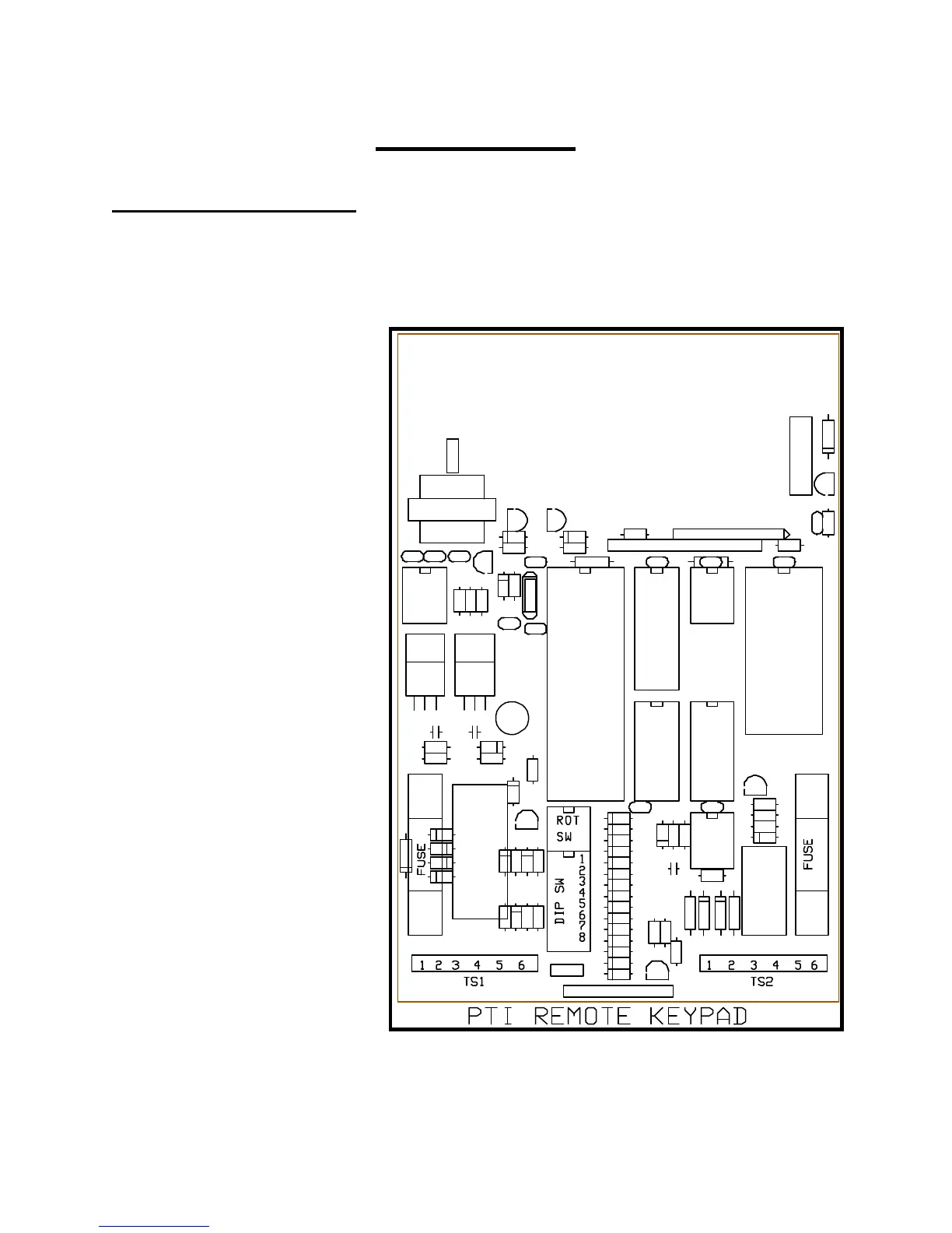
Figure Eleven is a diagram of
the circuit board found in the
front half of the Remote keypad.
The items of interest to the
installer are as follows:
(1) Depluggable terminal strip
TS1 with six terminals at
the bottom left of the circuit
board.
(2) Depluggable terminal strip
TS2 with six terminals at
the bottom right of the
circuit board.
(3) Power line fuse on the
bottom left side of the
board.
(4) Relay contact fuse on the
bottom right side of the
board.
(5) Red rotary switch near the
bottom center of the board.
(6) Eight position DIP switch
under the red rotary switch.