as follows:
TOWARD DCU AWAY FROM DCU
Red: +OUT Red: +OUT
Black: -OUT Black: -OUT
White: DOUT White: DINP
The two conductor switch wire may be hooked up in either order to the two end
connection points.
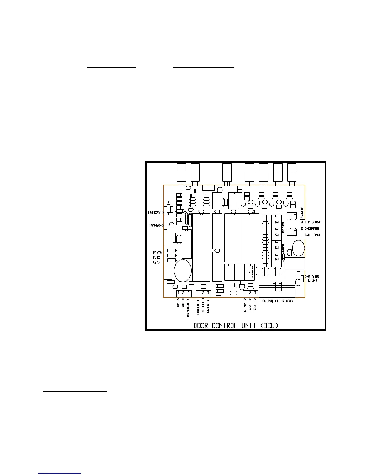
(5) Terminate the three conductor door to door wire on the bottom right terminal strip of
the DCU board as shown in Figure Seventeen. This terminal strip is numbered one
through three, left to right.
Be careful to terminate
the white wire under
screw number one, the
red wire under screw
number two, and the
black wire under screw
number three.
(6) Install the communication
wiring to the DCU boxes.
The RS485 com-
munication wire should be
a 22 gauge shielded
twisted pair for best
results. This type of cable
will contain a red
conductor, a bare shield
wire, and a black con-
ductor. The red wire
should be hooked to the
DATA+ terminal, the bare
wire to the SHIELD
terminal, and the black
wire to the DATA-
terminal. The terminal locations are indicated in Figure Seventeen. The RS485
communication cable will connect all keypads and DCU boxes in parallel to the PTI
Falcon base unit.
Mux Box Switches
There are four red rotary switches on the master DCU board. The top two switches are