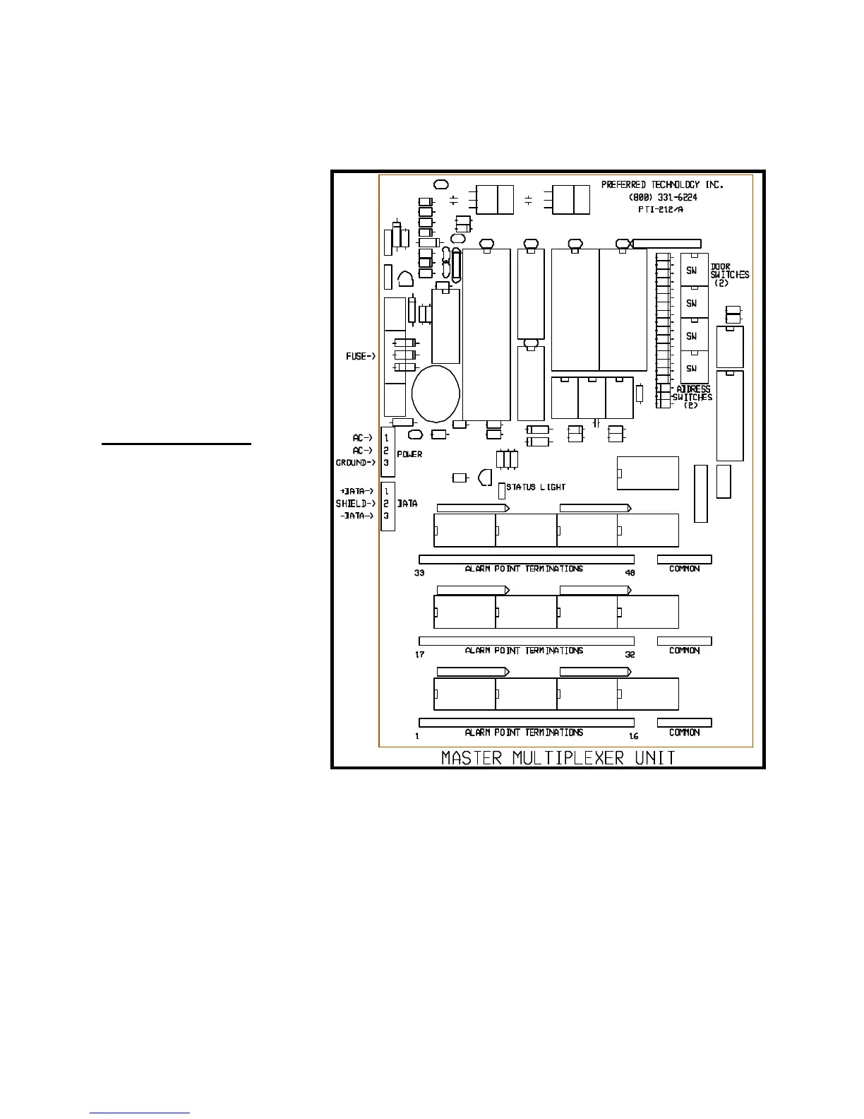
(4) Terminate the wires from the door to door wiring cable on the mux board depluggable
terminal strips. Figure Fourteen illustrates the board layout. There must be one
separate wire from each
door switch and a
common wire from all
door switches.
Terminate the separate
wires on the three
sixteen position terminal
strips, beginning with
position #1 on the
bottom left. The
common wire or wires
may be terminated on
any of the three four-
position terminal strips.
Mux Box Switches
There are four red rotary
switches on the master mux
board. The top two switches
allow you to set the board for
the number of doors actually
wired to the board. Dial the
two digit number into the
switches using a small
screwdriver. The switches
are read from bottom to top.
For example, thirty seven
doors would require the top
switch to be set to
seven
and the switch below it to be
set to
three
. If the board
controls more than ninety
nine doors, setting DIP
switch #1 to the
ON
position
will add one hundred to the two digit number of doors dialed into the red rotary switches.
Set the other two red rotary switches to the unit number desired for the mux box. The
boxes may be numbered in any order as long as each box has a unique unit number that is
not the same as any other mux box or keypad. It is typical to begin numbering the mux
boxes at one higher than the last remote keypad number. For example, if there are two
gate access keypads numbered one and two, then the mux boxes will be numbered three,
four, five, etc. These red rotary switches are also read bottom to top, so a remote number