set ON. The keypad only reads switch four at power up, so if you must change switch four,
momentarily kill power to the keypad after it has been correctly set.
Switch eight when ON, places a communication line terminating resistor across the RS485
data leads. This switch should be turned ON if the keypad is the last keypad on the RS485
communication wire, otherwise set it OFF.
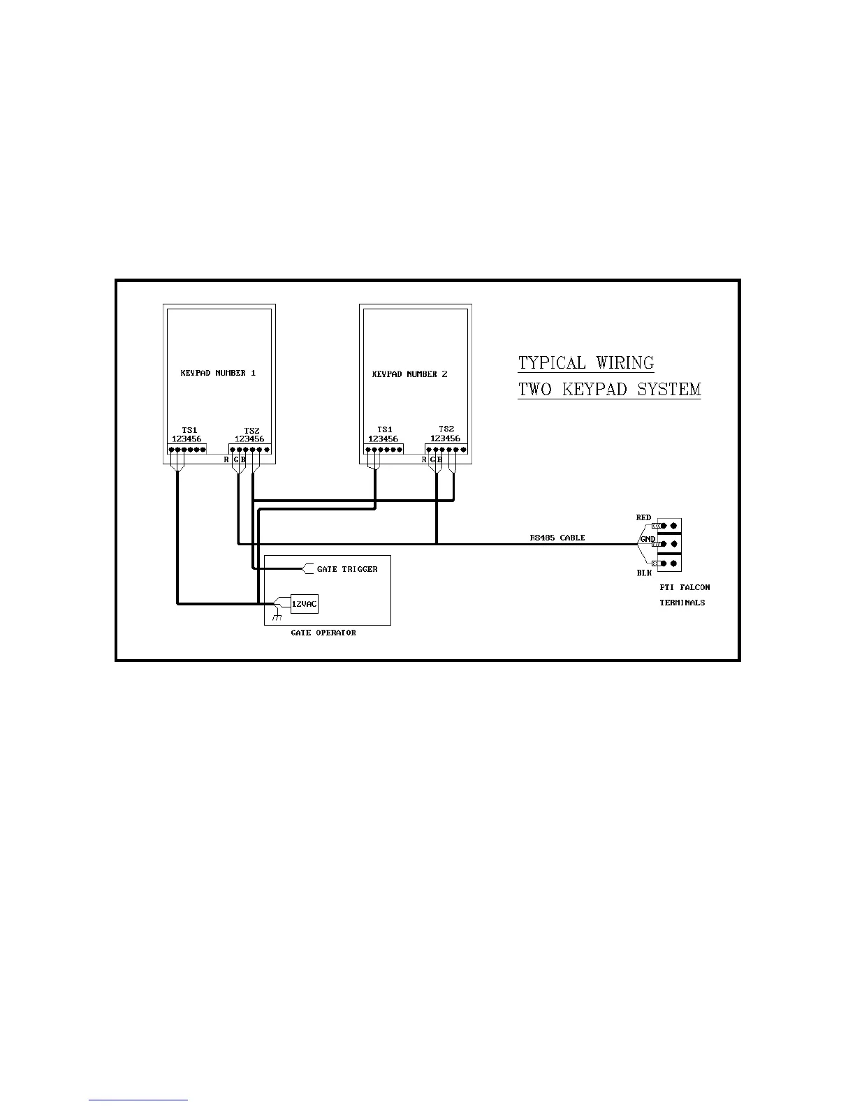
Figure Twelve illustrates a typical wiring scheme for a two keypad gate access system.
In this case, the twelve volt supply transformer for the keypad power has been located in the
gate operator. In some installations, it may be more advantageous to locate this
transformer in the office with the base unit.
With the RS485 communication scheme, a keypad can typically be located as far as four
thousand feet from the base unit. As the wire length increases, a shielded twisted pair
cable with ground wire becomes a necessity for proper operation.
Figure Twelve