24
3.6.3 ADD Switch Setting (Address Assignment)
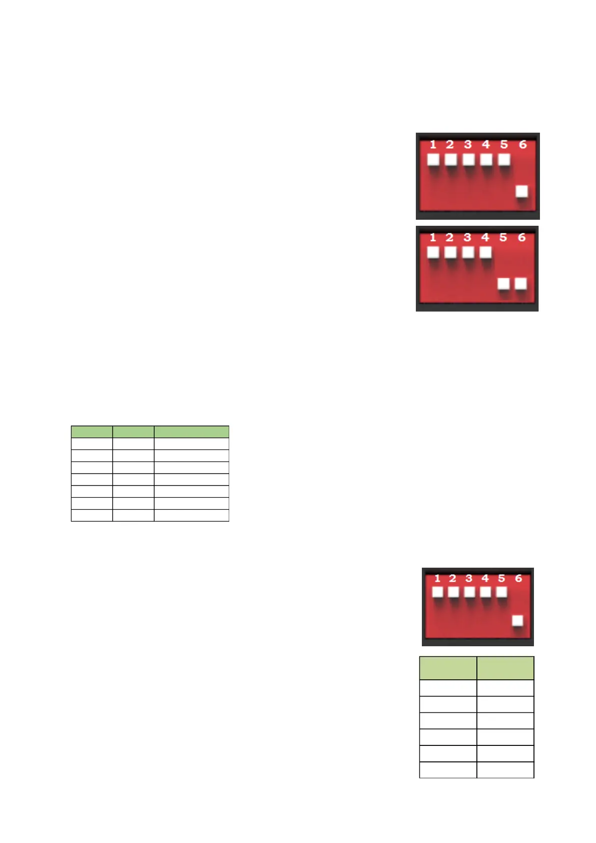
ADD Switch BMS is a 6 bit dial switches to manually distribute the
communication address of the battery system. Nether position is OFF,
means “0”. Upper position is ON, means “1”. 1
st
bit to 5
th
bit is for
address, and the 6
th
bit dial switch support a 120Ω resistance (Terminal
Resistance).
ADD Switch MBMS is a 6 bit dial switches to manually distribute the
communication address of the battery system. Nether position is OFF,
means “0”. Upper position is ON, means “1”. 1st bit to 4th bit is for
address, the 5th and the 6th bit dial switch support a 120Ω resistance
(Terminal Resistance).
3.6.3.1 Under communication for single BMS (battery string qty. 1 set)
The BMS’s first five bits must set in below <BMS’s Address Configure Table>. The last BMS’s terminal
resistance must set in “1” (X=1);
The address is configured follow ASCII code: (“X” is terminal resistance).
BMS’s Address Configure Table:
3.6.3.2 Under CAN Communication Mode between MBMS and BMS (battery string qty. ≤6 set)
The BMS’s first five bits must set in below <BMS’s Address Configure
Table>. The last BMS’s terminal resistance must set in “1” (X=1), and other
BMS’s terminal resistance must set in “0”.
The address is configured follow ASCII code: (“X” is terminal resistance).
BMS’s Address Configure Table:
The MBMS’s ADD Switch set with “000011”.
The last 2 bits are terminal resistances.
Note: the 1
st
to 4
th
bit dial for MBMS refer to 3.6.3.3
1 10000X 9 10010X 17 10001X 25 10011X
2 01000X 10 01010X 18 01001X 26 01011X
3 11000X 11 11010X 19 11001X 27 11011X
4 00100X 12 00110X 20 00101X 28 00111X
5 10100X 13 10110X 21 10101X 29 10111X
6 01100X 14 01110X 22 01101X 30 01111X
7 11100X 15 11110X 23 11101X 31 11111X
8 00010X 16 00001X 24 00011X 32 00000X