10 POWER CONNECTIONS
10.1 Mains Connection
The mains supply should be carefully wired to an a.c. mains supply using suitably rated 3 core cable with a current
capacity of not less than 5 amps. It should be connected to a fuse spur with a fuse rating of not more than 3 Amps. The
mains connections at the power supply input are coded as follows, L – Live, E – Earth and N – Neutral.
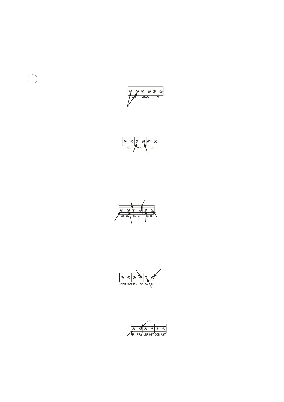
This product requires a hard-wired protective earth.
17V a.c.
The Atlas requires a supply of 17V a.c. from the power supply unit or transformer, with a current capacity of 1 amp.
Connect the 17V current to the terminals marked AC on the PCB.
10.2 Battery Connection
Battery Positive (+)
Battery Negative (-)
In order for the Atlas to operate if the mains power is cut a battery back-up is required. Refer to 10.5 for battery
specifications. Connect the battery to the terminals marked +BAT- on the PCB.
10.3 Bell, Strobe and Extension Speaker Connections
Strobe Positive (+) Strobe Negative (-)
Speaker Negative (-)
Speaker Positive (+)
Bell Trigger
Bell Positive (+)
NOTE: The bell Negative (-) should be returned to the BAT (-) connection on the PCB.
The bell tamper must be connected to a tamper zone or connected as end of line zone.
10.4 Remote Keypad ‘RKP’ Connections
Keypad Positive (+)
Keypad Data
Keypad Negative (-)
If more than one keypad is to be used, additional keypads can be wired in either daisy chain or star configuration.
The RKP tamper must be connected to global tamper.
10.5 Programmable Outputs
Programmable Output 2
Programmable Output 1
There are two programmable outputs which can be switched negative (-) to positive (+) or positive (+) to negative (-)
depending upon which system option is programmed.
Rins163 Issue 9 Page 23