12
QSC, LLC
4.3 Amplifier module
Overview
K.2 Series amplifier modules have high power capability and tons of fea-
tures packed into a custom module that fits into the back of K.2 enclosures.
The same hardware is shared between all models, with the only difference
being the DSP firmware and exterior labels noting the model. If compar-
ing the bill of material between the K8.2, K10.2 and K12.2, the electronic
components would be exactly the same. K.2 Series amplifier modules are
specifically designed for K.2 enclosures and transducers. They should not
be used in any other QSC powered loudspeaker.
The amplifier module is comprised of four separate PCB assemblies: the
AC line filter board, AMP/PSU board, input/DSP board, and LCD board.
The AMP/PSU board is a universal switch-mode power supply, working in
regions with 120V or 230V AC mains. The AMP/PSU board also contains
two class D output stages in a bi-amp configuration. The input/DSP board is
comprised of mostly analog/digital audio signal processing, physical input/
output connections, and peripheral control (LCD display, buttons, LEDs, po-
tentiometers) for the amplifier module. And finally, the LCD board contains
a liquid crystal display, rotary encoder, buttons, and debouncer circuitry.
Detailed information on the circuits in these boards is described in the next
sections.
Startup sequence
The startup sequence for K.2 series is similar to the original K series. The PWM controller at U15 charges itself up when
AC voltage is present above a certain threshold, approximately 85 Vac. Once U15 has charged up, the switch mode power
supply (SMPS) is switched on. During these first seconds, the class D amplifier circuits are disabled by default.
Once auxiliary voltages (±15V, ± 5V, and +12VLOW) rise on the secondary side of the transformer, the microcontroller
(MCU) and DSP will begin to boot. All audio outputs are muted in the DSP until the voltages at the AC monitor (circuit at
U9) and a couple other internal voltages (+15V, -15V, +5VA_A, and +3.3VD) are measured by the DSP and MCU through
ADC inputs. The voltages must be within bounds to continue. If the measured AC voltage is between 100 – 140 Vac, the
AC voltage doubler circuit is enabled. The heatsink temperature must also be within an operable range. The DSP and MCU
communicate over an SPI bus and both ultimately decide what to do next. If everything checks fine, the DSP and MCU will
allow audio output and enable the amplifiers (normal operation).
AC line filter board
The line filter board has an AC input and filtered AC output. The brown wire (AC line) comes from the power switch and
blue wire (AC neutral) come straight from the power inlet. When the power switch is turned on, the line filter circuit is ener-
gized. The filtered AC output goes to a wiring harness that connects to the AMP/PSU board.
A simple line filter attenuates electrical noise cou-
pled to the AC mains. It’s comprised of a fuse and
a pair of common-mode inductors with a cross-
line capacitor on each side. Between them, a pair
of differential-mode capacitors (C42 and C43)
connect to earth/ground. Resistor R42 discharges
the capacitors when the amplifier is disconnected
from AC mains. The fuse at location F41 on the
line filter board is not the standard glass tube type.
If the fuse blows, a new fuse cannot be easily
inserted back in. Soldering is required to replace
the fuse.
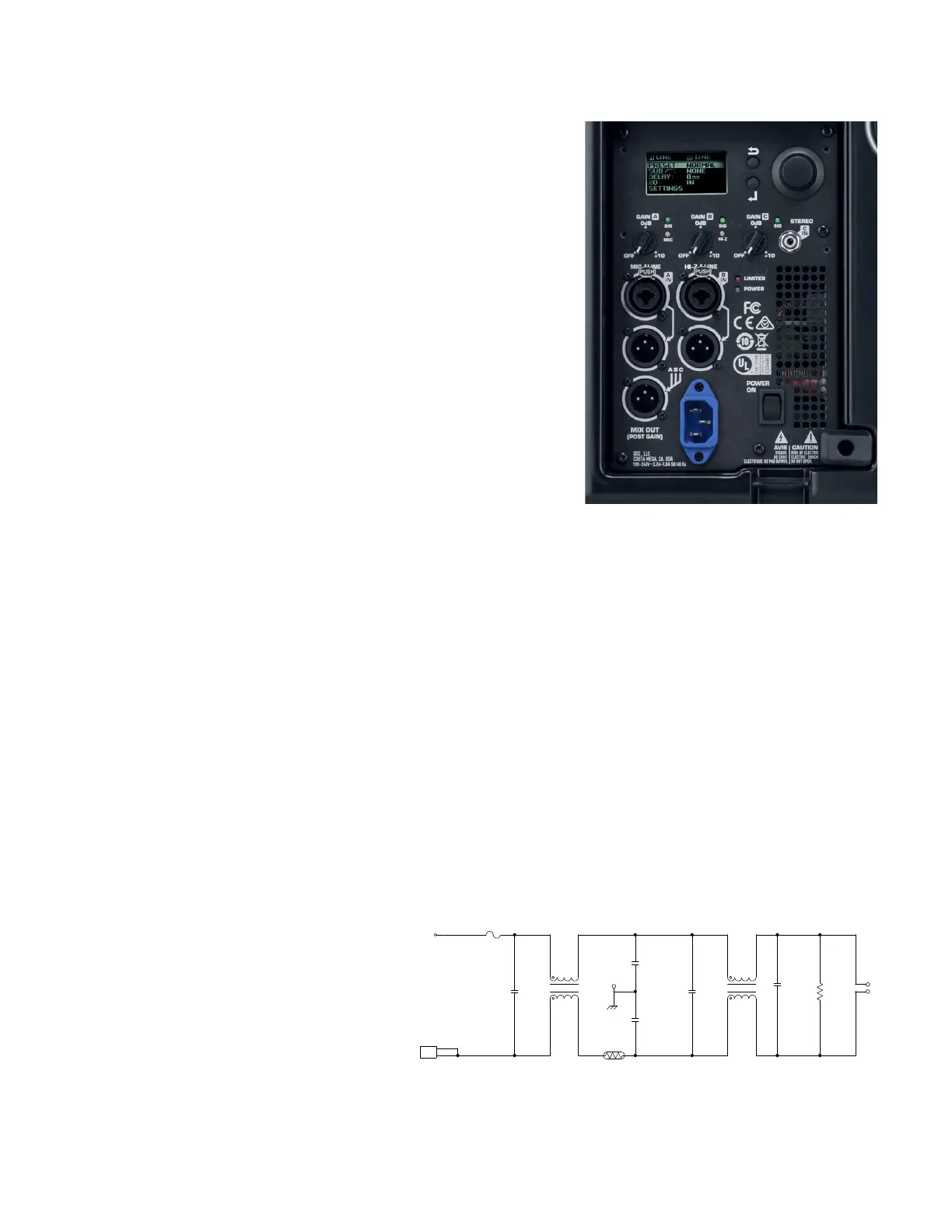
Figure 4.3.1 - Amplifier module
4MH
NTC
0.0033UF
250VAC
250V
6.3A
0.0033UF
20 PCNT
20 PCNT
0.1UF
390K
5 PCNT
250VAC
4MH
250VAC
20 PCNT
1/4W
0.68UF
20 PCNT
250V
20 PCNT
0.68UF
250V
R41
MTG41
J41
W41
C41
L41
C43
C42
C44
L42
C45
R42
W42
NEUT2
LINE2LINE1
NEUT3
LINE3
NEUT4NEUT1
LINE4
4
3
2
1
B1 B2
A2A1
C1
B1 B2
A2A1
2
1
Figure 4.3.2 - AC line filter circuit
 Loading...


