21
TD-001517-01
K.2 Series Service Manual
5.5 Low frequency transducer
The LF transducer can be removed and reinstalled without removing
the baffle.
Removal
8. Follow the removal instructions in “5.2 Front grille”.
9. Place the speaker on it’s back (or in monitor wedge position) so
the LF transducer doesn’t fall out after the screws are removed.
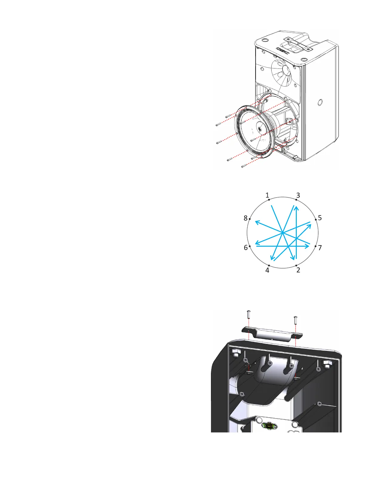
10. Remove 8 hex screws around the perimeter of the transducer’s
frame as shown in Figure 5.5.1.
Note: A specific hex bit should be used to remove these screws.
A standard hex bit may easily strip the heads on the screws.
11. Partially lift the transducer out of the speaker assembly.
12. Disconnect the green (+) and green/black (-) wires from the LF
transducer’s terminals. The faston connectors have a locking tab on
them that must be pressed to release the connector from the speaker
tab.
13. Fully remove the transducer from the speaker assembly.
Installation
1. Place the speaker on it’s back (or in monitor wedge position).
2. Connect the green (+) and green/black (-) wires from the LF transducer’s
terminals.
Important note: This connection must have high retention force! Crimp new
fastons (0.205” or 5.21 mm female, 14–16 AWG, insulated straight, with
locking tab) to the wiring harness if the old ones are weak or not functional.
3. Gently lower the LF transducer into the speaker assembly, also noting the
original LF driver orientation (the +/- LF tabs should be at 2 o’clock).
4. Fasten the 8 screws that secure the transducer to the baffle in a star pattern.
Note: Be very careful when installing the screws. The screwdriver can easily
slip and pierce a hole in the surround or cone of the transducer.
5.6 Handles, feet, and pole mount
Handle removal and installation notes
• The handle is secured to the enclosure with machine screws and
mounting plates (on the interior of the enclosure).
• Access to the interior of the speaker assembly is usually required
to remove and install the handles, due to the limited access of the
mounting plate.
• The only way to access the interior of the enclosure is to remove
the baffle assembly. See removal instructions in “5.3 Front baffle”.
• If the machine screw is removed accidentally, the threads on
the mounting plate may not align with the enclosure holes. The
mounting plates can slide back and forth on the rails inside the
enclosure, so make sure they are aligned correctly.
• Reapply a small amount of thread locking fluid to the mounting
plate when replacing the handles.
Figure 5.5.1 - LF transducer
Figure 5.5.2 - LF transducer fasten
sequence
Figure 5.6.1 - Handle, screws, and mounting plates
inside the enclosure.
 Loading...


