38
QSC, LLC
8. Troubleshooting tips
For additional troubleshooting information on K.2 Series powered loudspeakers, please see the “K.2 Series Service Trouble-
shooting Guide” document available on the QSC Service Partner Portal. QSC will frequently revise the Troubleshooting
Guide document as new common failures are found.
The troubleshooting contents inside this service manual are strictly tips that will help you troubleshoot the loudspeaker.
Safety first
• The filter capacitors between PRI_HI / PRI_LO and VSS / VDD store a lot of energy! The voltage on these rails takes at
least 10 minutes to fully discharge. If you are performing rework or repair, always discharge both voltage rails.
• PRI_LO is NOT chassis ground. Do not use an oscilloscope or DMM connected to earth ground.
8.1 General tips
AC mains fuse
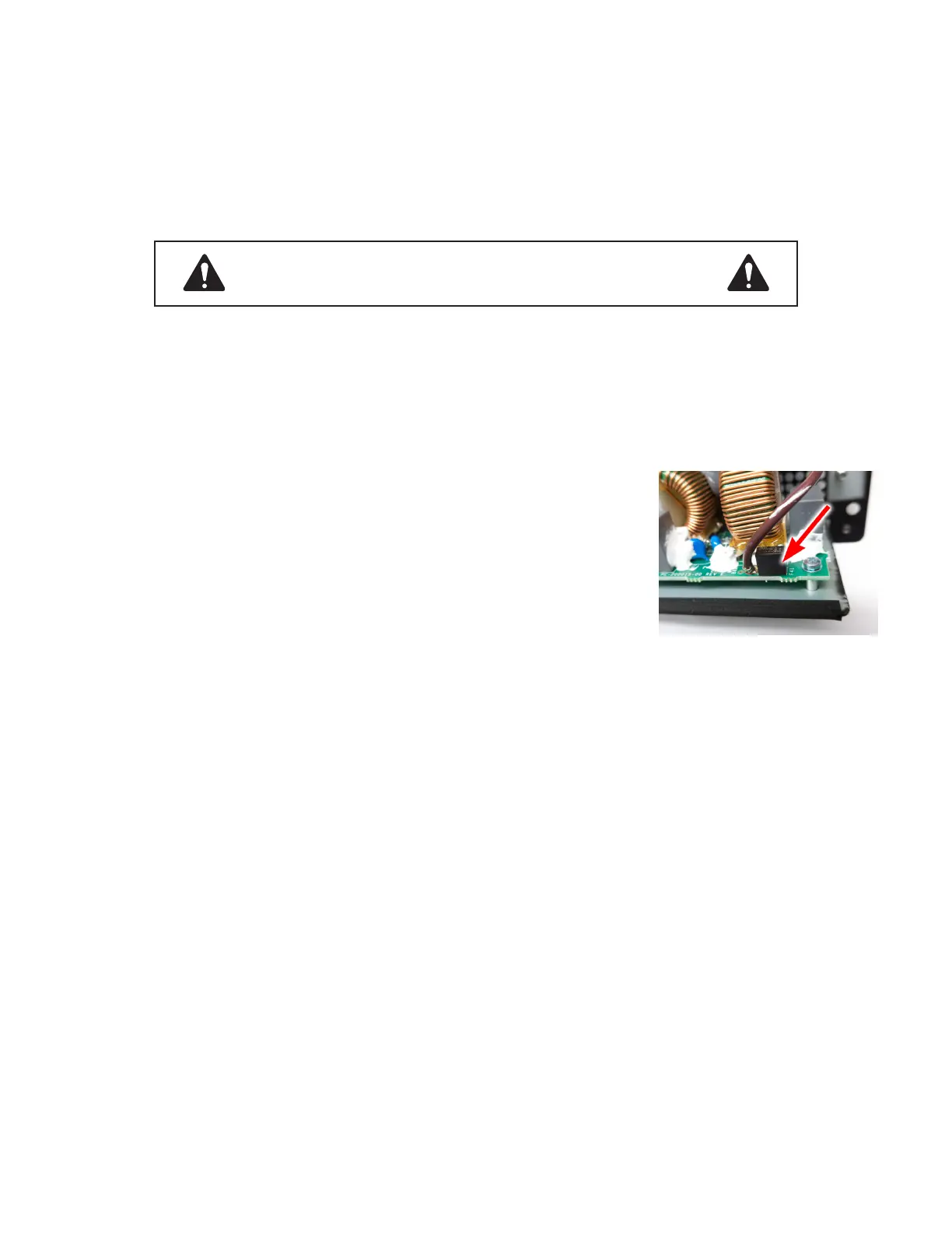
• If the AC mains fuse blows, a soldering iron is required to replace it. To measure for
an open AC fuse, use the tip noted in “8.2 Testing the AC mains fuse and line filter
components”.
• The fuse is not field-replaceable by an end-user, see location in Figure 9.14.1.
Power supply
• If the PSU is not running and no LEDs are turning on, check the voltage across PRI_
HI and PRI_LO for approximately 320 - 340▲Vdc. Check the voltage across resistor
R147 for approximately 55▲Vdc.
• If the PSU does not come out of a pulse-skipping mode, check for shorted diodes D23, D24, and D51. Also check U2,
Q8, and Q7 (in the HF amplifier section).
• If excess transformer noise is heard in normal mode, check the PWM at U15. Also check U4 for bad solder or failed
components nearby.
Power supply modes: active vs. passive
The SMPS is in active clamp mode in these scenarios:
• During normal operation
• When the MOSFET Q13 is switching
• When the power supply is idling, but not yet in standby mode (passive clamp)
The SMPS is in passive clamp mode in these scenarios:
• During standby operation (after no input signal has been detected for 3 minutes)
• When MOSFET Q13 is not switching and is acting as a diode.
Amplifier circuit
• If VSS/VDD are dipping or the PSU relay is clicking when amplifiers are enabled, check for shorted diodes in one or both
channels over-current protection circuits.
• If only one amplifier is not running, check the +12VLOW rail to that channel. Check for poor solder connections. Check
the gate driver IC and also the green LED in that channel.
• If both amplifiers aren’t running, there is a universal issue with the voltage rails that the amplifier circuits uses. Check the
±15V, ± 5V, and +12VLOW rails in the AUX OUTS circuit of the power supply.
WARNING: RISK OF ELECTRICAL SHOCK
High Voltage is present in the main power supply. Proceed with caution.
Figure 8.1.1 - Non-replaceable AC
mains fuse location at F41.
 Loading...


