28
QSC, LLC
6.4 LCD board
Removal
To remove the LCD board from the amplifier module chassis, the input/DSP board
must first be removed for access.
1. Follow the removal steps in “6.3 Input/DSP board”.
2. Remove the large knob from the rotary encoder shaft (Figure 6.3.1).
3. Remove the 4 machine screws that secure the LCD board to the chassis stand-
offs as shown in Figure 6.4.1.
4. Remove the LCD board out of the chassis and set aside.
Important note: Two small plastic buttons (Enter and Return) may fall off the
LCD board when removing it. When replacing the LCD board with a new one,
reuse the buttons.
Installation
The input/DSP must be removed from the chassis before installing the LCD board.
1. Prepare the new LCD board for installation.
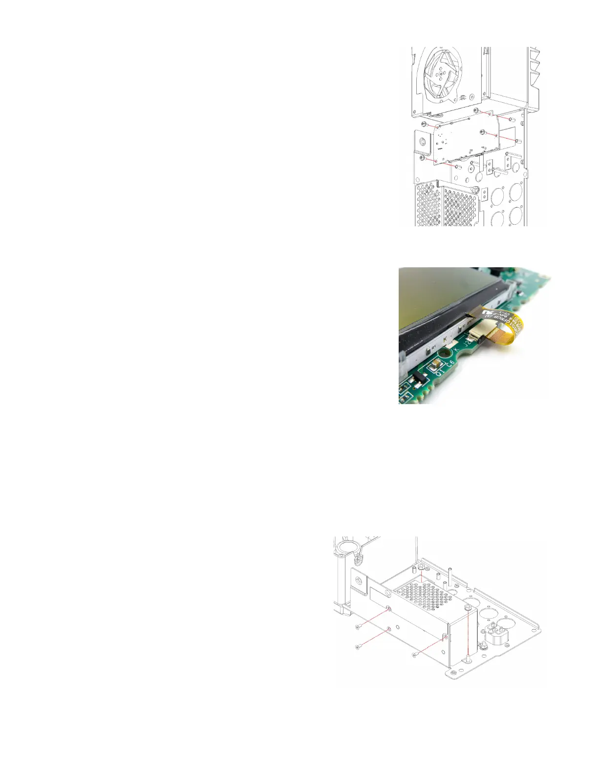
2. Verify the ribbon cable connection on the LCD display is secure and in the
locked position. See Figure 6.4.2.
3. Insert the two small plastic buttons to their appropriate locations.
4. Place the LCD board into the chassis, verifying the buttons are still in place.
5. Fasten the 4 machine screws that secure the LCD board to the chassis stand-
offs as shown in Figure 6.4.1.
6. Install the large knob onto the rotary encoder shaft.
6.5 EMI shield and AC line filter board
Removal
The EMI shield can be removed without removing the input/DSP board, but it is not recommended due to limited access
and specialty tools. The easiest way to remove the AC line filter board is to first remove the input/DSP board, as noted in
the instructions below.
1. Follow the removal steps in “6.3 Input/DSP board”.
EMI shield removal
2. Cut the zip tie at the top corner of the EMI shield to loosen the
AC wiring harness.
3. Remove the 3 machine screws that secure the EMI shield as
shown in Figure 6.5.1.
4. Remove the 2 nuts from the threaded standoffs using a 7mm
wrench or nut driver. See Figure 6.5.1.
5. Lift the EMI shield out of the chassis and set aside.
Figure 6.4.1 - LCD board assembly
Figure 6.4.2 - Ribbon cable on LCD
Figure 6.5.1 - EMI shield assembly in amplifier chassis
 Loading...


