19
TD-001517-01
K.2 Series Service Manual
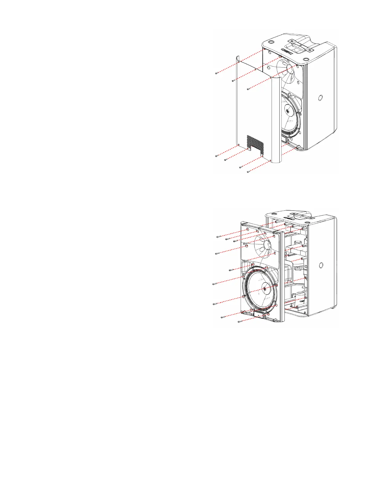
5.2 Front grille
Removal
1. Remove the 7 screws that attach the front grille to the baffle as
shown in Figure 5.2.1.
2. Using a putty or butter knife, pry the grille outward and remove
it. If the grille is stuck, gently pry along the sides in multiple loca-
tions until the grille becomes loose enough to remove.
Installation
1. Verify that the gasket along the sides of the grille is still in place.
If you are replacing the grille with a new one, install new gasket
to reduce vibrations between the grille and baffle.
2. Fit the side edges of the grille in the space between the baffle
and enclosure. Press down gently. Be careful not to bend the
grille. If the grille does not fit in the space, the baffle may need
to be realigned.
3. Fasten the 7 screws that secure the grille to the baffle.
5.3 Front baffle
Removal
1. To access the front baffle, the front grille must be removed.
Follow the Removal instructions in “5.2 Front grille”.
2. Remove all screws that secure the baffle to the enclosure. See
Figure 5.3.1.
Note: An extra long #4 hex head bit (like p/n WERA 840/4 IMP)
is required to access the 2 screws in the middle of the baffle.
3. Partially lift the baffle assembly away from the main enclosure to
separate them.
4. Disconnect the molex connector from the rear of the amplifier
module (inside the cabinet).
5. You may now fully remove the baffle assembly from the main
enclosure.
Installation
It’s recommend that the LF and HF transducers are installed before
reinstalling the baffle to the main enclosure assembly.
1. Verify that the positive and negative terminals on the LF and HF transducers are connected securely to the wiring har-
ness.
2. Verify that the gasket is properly installed around the edge of the baffle.
3. Reinstall all acoustic insulation in both the main enclosure assembly and baffle assembly.
4. Gently place the baffle assembly into the main enclosure. If possible, connect the molex connector to the amplifier
module.
Note: Connecting the wiring harness to the amplifier module at this stage can be difficult. Perform that step after the
baffle has been installed by removing the module, connecting the harness, and reinstalling the module.
5. Verify that the small gap between the sides of the main enclosure and the baffle are even. Both sides of the front grille
must fit inside these gaps.
6. Fasten the screws that secure the baffle to the enclosure, starting with the corner screws. See Figure 5.3.1.
Figure 5.2.1 - Front grille assembly
Figure 5.3.1 - Baffle assembly and enclosure
 Loading...


