46
QSC, LLC
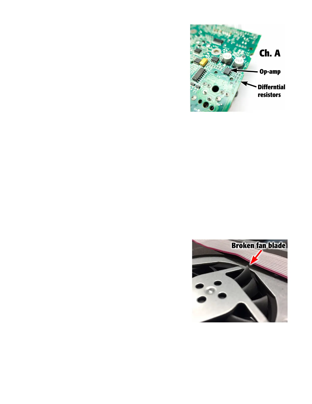
8.10 Input section failure
Transient voltages originating from external sources input to the XLR, 1/4”,
or 3.5mm jacks could cause input circuit failure in the differential section,
especially to differential resistors. As with most input circuit failure, multiple
components in the input circuit can fail. The higher the intensity and length
of time of the transient voltage seen at the input, the more components
will fail downstream.
Symptoms
• Channel A, B, or C does not receive input signal
• Without an input connected, channel A, B, or C outputs noise when the
gain is increased
• Without an input connected, the green signal LED always on
Failure verification
• When a known good signal (sine wave recommended) is input to the failed channel, signal integrity is compromised
after the op-amp output of U3 or U4 (on the input/DSP board).
Repair notes
• Before repairing, try to determine if the end user had MIC (Ch. A) or INST (Ch. B) modes on. These modes enable high
gain in the differential op-amp circuits, which could cause additional damage upstream.
• Channel A (MIC LINE) is much more susceptible to failure than the other channels. The differential resistors R3 and R4
are usually the first component to fail.
• High frequency oscillations on the input could cause the inductors right after the XLR inputs to fail.
• If all 3 signal LEDs are on without input, it may be related to a different failure in the +12VLOW circuit (see page 43).
• After repairing, pay close to the gain section when bench testing the amplifier module
8.11 Fan issues and overheating
A functional fan is required for normal use of the K.2 series. If the fan does
not work, the amplifier module will easily overheat, go into thermal protec-
tion, and shutdown the amplifiers. Most fan issues are related to broken/
stuck fan blades, disconnected fan wires, or shorted fan circuitry.
Symptoms
• Overheating - amplifier heatsink is hot when touched.
• Audio suddenly stops
Failure verification
• Fan does not spin when temperature is above 50 C (you can use Test
Mode App to view the temperature on the LCD screen, rather than actu-
ally measuring the temperature).
Repair notes
• The root cause may simply be a disconnected fan wire.
• Check for broken or stuck fan blades as in Figure 8.11.1. Try to spin the fan with your fingers. It should freely move.
• Disconnect the fan. Measure the voltage across the fan pins at J7 on the input/DSP board when temperature is over 50
C. There should be at least 9 volts across the fan pins. If not, then the fan drive circuit has failed. Check transistor Q2,
resistor R28, and the +15V_A power rail.
Figure 8.10.1 - Differential resistors in Ch. A
Figure 8.11.1 - Check for broken fan blades if
there is an over temperature condition.
 Loading...


