32
QSC, LLC
7. Testing
7.1 Requirements
Hardware
• Digital multimeter with RMS AC voltage and current
• Digital clamp-on ampere meter
• Dual-trace oscilloscope
• Audio distortion analyzer with built-in low-distortion audio sine
wave generator and resolution of 0.01%, 20 - 20k Hz (or better)
• Non-inductive load resistors, configurable as 16Ω (min. 225 watts
capacity), as 2Ω (min. 1000 watts capacity).
Note: Either connection of the test load should not be connect-
ed to any electrical ground system.
• Variable AC voltage source, such as a Variac or Powerstat variable
transformer, with a rated current capacity of up to 25A for 120V
or 12A for 230V.
• Class D filter, i.e. Audio Precision AUX-0025
• Custom K.2 series test adapter
Molex pinout (output connector)
The molex jack, which connects to the speaker’s internal wiring harness, is located
on the back of the amplifier module. The LF/HF outputs and front LED can be tested
via the molex jack. See the pin-out diagram in Figure 7.1.1.
K.2 Series test adapter
For testing an amplifier module under load or viewing the output waveform on an oscilloscope, a test adapter can be easily
constructed by using a K8.2, K10.2, or K12.2 spare wiring harness. Place a compatible connector with your test load bank
(like a dual binding post connectors as in Figure 7.1.2) or Speakon connectors. Please refer to the wire colors diagram and
wiring harness part lists below.
Audio Precision (AP) Test Procedures
If an Audio Precision distortion analyzer is available,
please contact QSC for the test procedure files.
They are available upon request.
Figure 7.1.1 - Amp output connector
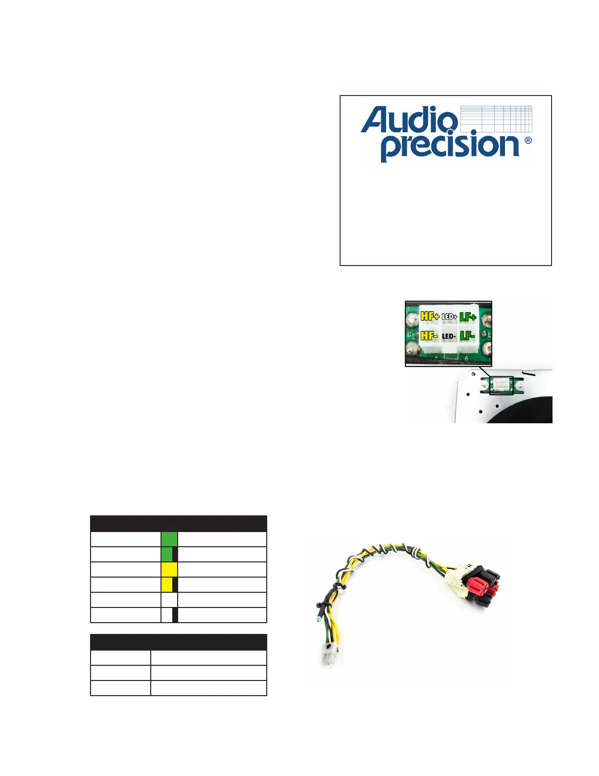
Figure 7.1.2 - K.2 Series test adapter with dual binding
post connectors, made from a K.2 wire harness.
Wire Color Connection
Green LF +
Green / black LF -
Yellow HF +
Yellow / black HF -
White Front LED anode
White / black Front LED cathode
Model Wire harness p/n
K8.2 WC-000613-00
K10.2 WC-000614-00
K12.2 WC-000615-00
*Any wire harness part number can be
used as a test adapter for all models
 Loading...


