44
QSC, LLC
8.8 Testing the input/DSP and LCD boards
Swapping known good boards to isolate failure
One of the easiest troubleshooting steps is to swap a board with a known good one. It is recommended to keep a “golden
unit” of each board in your lab. It’s very simple to swap the input/DSP and LCD boards, even with the original boards still
installed in the amplifier chassis.
Important note: If performing a swap with the original board installed in the chassis, place some insulation material
between the original and golden board to avoid electrical shock and shorting.
Input/DSP board swap
1. Remove the 3 larger ribbon cables (ignore the 2-pin ones) from the original input/DSP board.
2. Connect the 3 ribbon cables to their appropriate locations in the golden input/DSP board. See Figure 8.8.1.
3. Verify all basic functions with the golden input/DSP board. If they fix the original problem, replace the input/DSP board
with a new one.
LCD board swap
1. Remove the 2 larger ribbon cables that connect the input/DSP board to the LCD board.
2. Connect the 2 ribbon cables coming from the LCD board to their appropriate locations on the input/DSP board. See
Figure 8.8.2.
3. Verify all basic functions with the golden LCD board. Verify that the rotary encoder, buttons, and LCD screen work
correctly. If they fix the original problem, replace the LCD board with a new one.
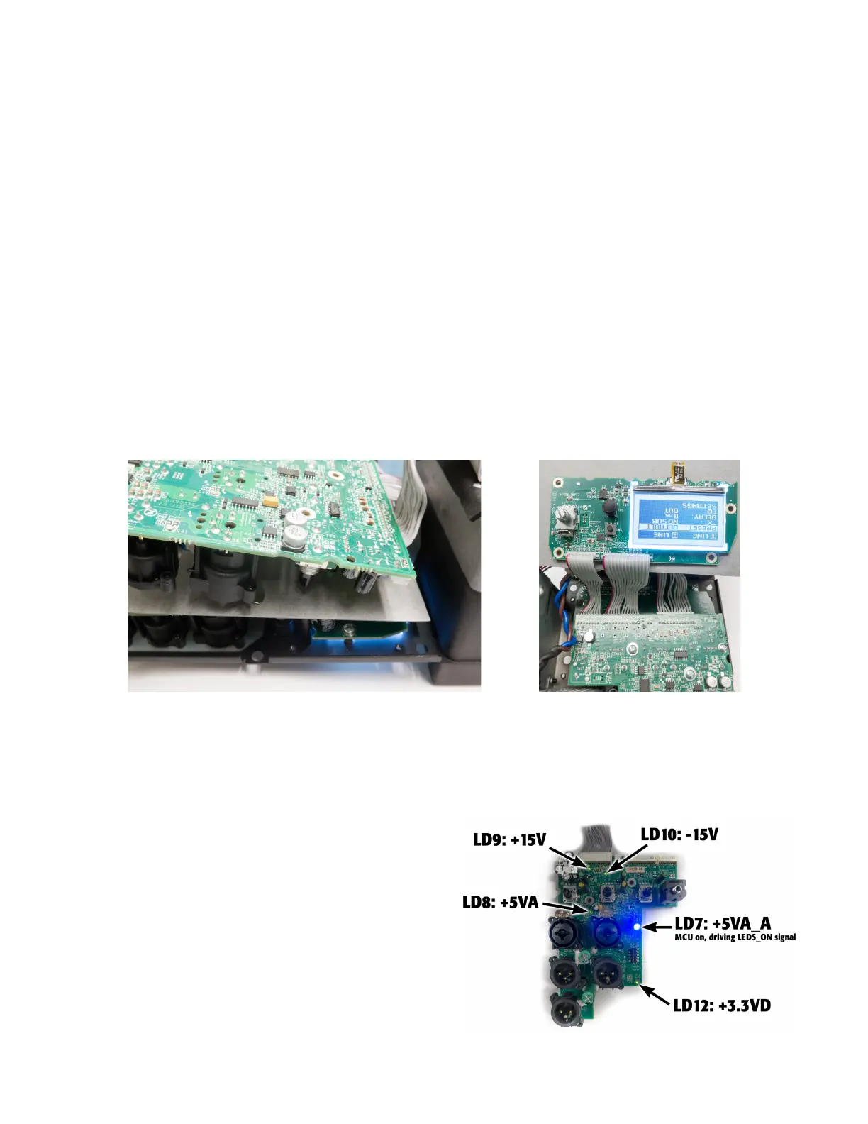
LEDs on the input/DSP boards
Monitoring the blue power LED and several green LEDs on the input/DSP board may aide in troubleshooting. See Figure
8.8.3 for location of the LEDs on the board. The input/DSP can be powered on outside the chassis with or without the LCD
board connected.
• Blue LD8: If LD7 is steady, the +5V_A rail is good and MCU is
working (or at least driving the signal LEDS_ON, which turns
on the blue LED).
• Green LD8: If LD8 is steady, the +5VA rail is good.
• Green LD9: If LD9 is steady, the +15V rail is good.
• Green LD10: If LD10 is steady, the -15V rail is good.
• Green LD12: If LD12 is steady, the buck regulator at U19 is
working correctly and the +3.3VD rail (which powers the
MCU and DSP). If the LED is pulsing, check the +15V input
from the AUX power supply, the buck regulator components,
and circuits that use the +3.3VD rail.
Figure 8.8.1 - Testing with a golden input/DSP board (verified) Figure 8.8.2 - Testing with a golden
LCD board
Figure 8.8.3 - LED locations and associated voltage rails
 Loading...


