47
TD-001517-01
K.2 Series Service Manual
8.12 Front LED
The most common cause of front LED malfunction is a bad LED or internal wiring harness. The LED drive circuit is almost
never an issue.
Failure verification
• Front LED does not turn on (after verification that the LED is turned on through the LCD menu)
Repair notes
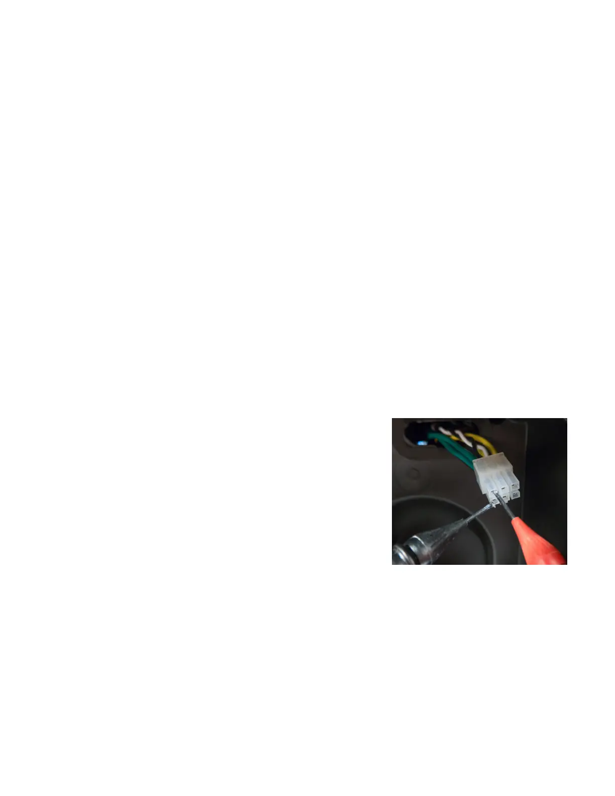
• It’s easier to check the front LED from the rear of the speaker through the molex connector. This will save time.
• Use a DMM in diode-check mode to apply voltage across the wiring harness at the molex connector pins. If the LED
does not illuminate, either the wiring harness is pinched/cut or the LED is out.
• To replace the LED, you must remove the grille and baffle from the enclosure.
• Separating the baffle assembly from the enclosure is the easiest way to replace the LED and check the wire harness.
• Use the K.2 test adapter to verify the amplifier module is outputting the LED signal. The blue LED on the test adapter will
illuminate if the LED signal is good.
8.13 Internal wiring harness
Sometimes the wires to the LF transducer (green and green/black) or HF transducer (yellow and yellow/black) disconnect
from the transducer terminals because they were not properly locked into place during assembly.
Symptoms:
• Missing or intermittent high and/or low frequencies
• Crackling noises in loudspeakers
Failure verification:
• A faston connector is disconnected from one of the terminals on the LF or
HF transducers.
• A wire is loose inside the molex connector that connects to the amplifier
Repair notes:
• Making measurements from the rear of the speaker (after removing the am-
plifier module) at the 6-pin molex connector can quickly provide information
about the condition of the transducers and front LED:
• The LF transducer (green wires) measures approximately 1.6 ohms
• The HF transducer (yellow wires) measures approximately 14 ohms
• The front LED can be turned on (illuminated) if you place your DMM
in diode-check mode.
• The faston connectors have latches that lock the connector in place. Gently
tug on the wires after connecting them to the transducer terminals to verify
that they are locked.
• Inspect all six wires in the wiring harness. Gently pull each one separately to make sure it is well secured in the Molex
connector. If any wire is loose and easily pulls out of the connector, replace the wiring harness assembly - do not repair it.
• The wiring harness should be slack enough to not put excessive stress on the connections, but taut enough that the
wires will not flop around and possibly make noise. If the harness wires are too taut, cut off the tie-wraps and install new
ones in a way that provides more slack. Attach the wires to the driver terminals, while making sure the polarity is correct.
• Plug a low-distortion audio sine wave generator into a 1/4” or XLR input connection on the amplifier module. Gradual-
ly sweep the frequency from 20 Hz to 20 kHz. All frequencies should be audible and free of distortion or rattling. You
should notice the sound crossing over from the woofer to the horn at about 2 kHz. If one of the transducers is discon-
nected internally because of the wiring harness, it will be very obvious with the sine-wave sweep.
Figure 9.14.1 - Making transducer impedance
measurements at the molex connector.
 Loading...


