27
TD-001517-01
K.2 Series Service Manual
6.3 Input/DSP board
Removal
1. Follow the removal steps in “6.1 Back cover”.
2. Disconnect all 5 ribbon cables from the input/DSP board (Figure 6.2.2).
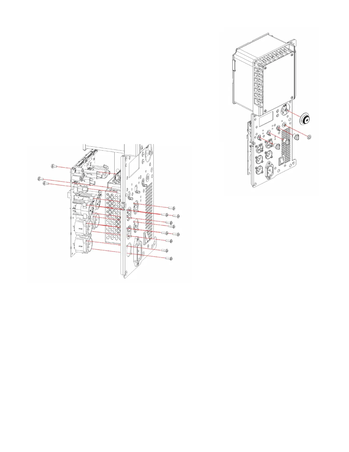
3. Remove the 3 gain knobs from the front of the amplifier module. See
Figure 6.3.1. The rotary encoder knob doesn’t need to be removed.
4. Remove the nut on the 3.5mm jack using a 10mm wrench or nut driver.
5. Remove the 10 plastite screws that secure the XLR connectors to the
front panel as shown in Figure 6.3.2.
6. Remove the 3 machine screws that secure the input/DSP PCB to the
chassis standoffs as shown in Figure 6.3.2.
7. The input/DSP board can now be removed from the amplifier module.
Installation
1. Prepare the input/DSP board for installation. Verify the LCD board is already mounted to the chassis because it cannot
be installed after the input/DSP board is already mounted.
2. Insert the input/DSP board into the chassis.
Important note: When mounting the input/DSP board into the chassis, the latches on the input XLRs must be inserted
into the holes on the chassis first. Once complete, verify that the LEDs on the input/DSP board are properly aligned
before proceeding to next steps. Fastening the screws without aligning the LEDs into the chassis holes can smash or
bend the LEDs.
3. Fasten the 3 machine screws that secure the input/DSP PCB to the chassis standoffs as shown in Figure 6.3.2.
4. Fasten the 10 plastite screws that secure the XLR connectors to the front panel as shown in Figure 6.3.2.
5. Fasten (by hand) the nut on the 3.5mm jack using a 10mm wrench or nut driver. Do not over-torque!
6. Install the 3 gain knobs and 1 rotary encoder knob (if removed) to their appropriate locations. See Figure 6.3.1.
7. Connect all 5 ribbon cables back to their original locations on the input/DSP board as shown in Figure 6.2.2.
Figure 6.3.1 - Knobs and 3.5mm jack nut
Figure 6.3.2 - Input/DSP board assembly to chassis front plate
 Loading...


