29
TD-001517-01
K.2 Series Service Manual
AC line filter board removal
The brown (line) and blue (neutral) wires coming from the AC
line filter board are routed to a jack on the AMP/PSU board.
6. Remove the metal cover to disconnect the AC wiring har-
ness from the AMP/PSU board.
7. Disconnect the faston connectors from the AC line filter
board.
8. Remove the 5 machine screws that secure the board to
the chassis standoffs as shown in Figure 6.5.2.
9. Remove the AC line filter board from the chassis and set
aside.
Installation
AC line filter board installation
1. Prepare the AC line filter board for installation. Adjust any AC wires and reroute accordingly.
2. Align and install the AC line filter board onto the chassis standoffs.
3. Fasten the 5 machine screws that secure the board to the standoffs as shown in Figure 6.5.2.
4. If required, route the AC wiring harness and connect it the corner of the AMP/PSU board. Verify the connector latch is in
the locked position. Gently tug on the wiring harness to verify sufficient latching.
EMI shield installation
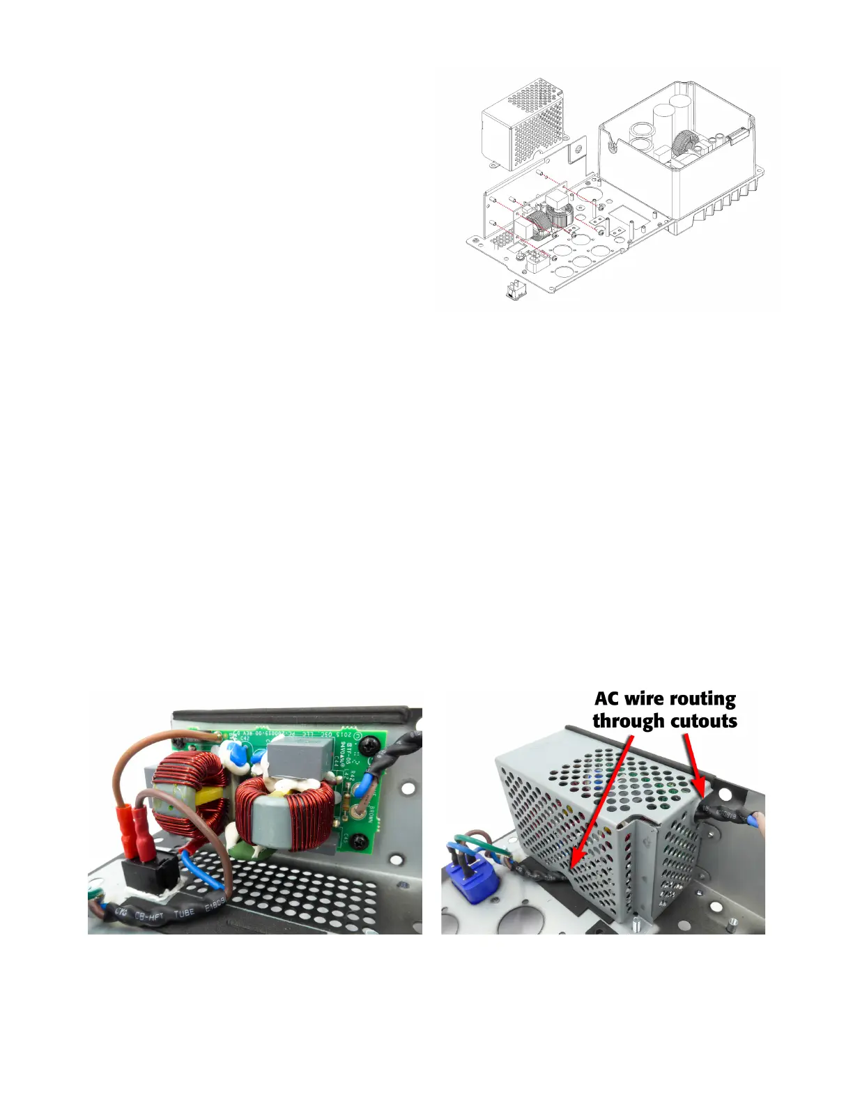
5. Carefully install the EMI shield into the chassis. Verify the AC wiring dressing at the bottom and sides of the shield to
ensure they are not pinched. See Figure 6.5.4.
Caution: High voltage on the AC wires is present. Verify that the AC wires are not pinched or loose!
6. Fasten the 2 nuts to the threaded standoffs using a 7mm wrench or nut driver. See Figure 6.5.1.
7. Fasten the 3 machine screws to secure the EMI shield to the chassis as shown in Figure 6.5.1.
8. Install the zip tie at the top corner of the EMI shield to secure the AC wiring harness. Trim excess.
Important note: AC wire routing and placement is very critical. If these installation steps are not done correctly, the AC
line could induce noise and cross-talk into the input/DSP circuits.
Figure 6.5.2 - AC line filter board assembly to amplifier chassis
Figure 6.5.3 - Faston connection through power switch Figure 6.5.4 - AC wiring guideline through EMI shield
cutouts
 Loading...


