22
QSC, LLC
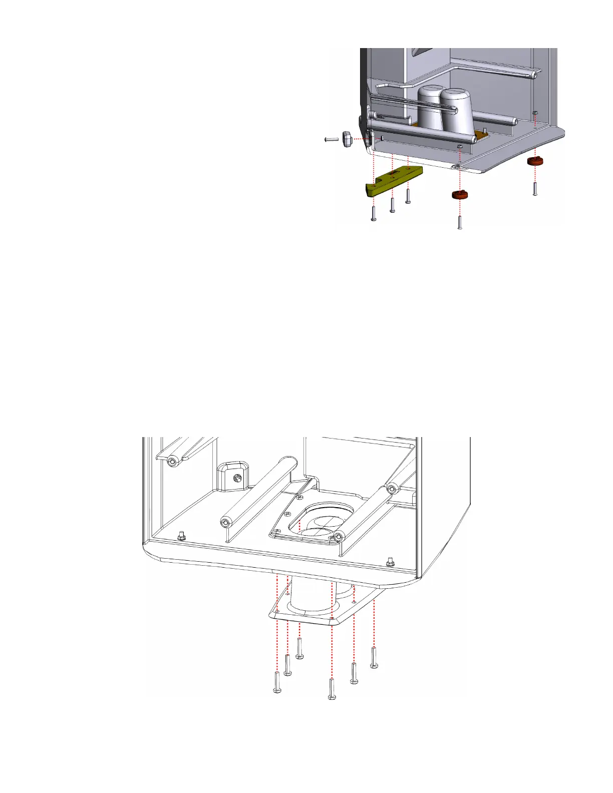
Rubber feet removal and installation notes
• The round rubber feet on the bottom of the enclosure are
secured with machine screws and nuts (on the interior of
the enclosure).
• The rectangular rubber feet on the sides of the enclosure are
also secured with machine screws and nuts (on the interior
of the enclosure). These rubber feet are intended for placing
the loudspeaker on its side in the monitor position.
• The large rubber foot on the bottom of the enclosure is se-
cured with 3 machine screws. One of the machine screws is
fastened to a nut on the interior of the enclosure in a deep,
hard-to-reach corner. The other two machine screws are
fastened to threads on the pole-cup mounting plate.
• Access to the interior of the speaker assembly is required to
remove and install all rubber feet.
• The only way to access the interior of the enclosure is to
remove the baffle assembly. See removal instructions in “5.3 Front baffle”.
• Reapply a small amount of thread locking fluid to the nuts when replacing the rubber feet.
• Refer to Figure 5.6.2.
Pole-cup removal and installation notes
• The pole-cup piece is secured to the enclosure with machine screws which are fastened to threads on the pole cup
mounting plate.
• The pole-cup piece can be removed from the exterior of the speaker enclosure. Access to the interior is not required.
• Reapply a small amount of thread locking fluid to the nuts when replacing the pole-cup piece.
• Refer to Figure 5.6.3.
Figure 5.6.2 - Rubber feet in various locations on enclosure.
Figure 5.6.3 - Pole cup piece and mounting plate inside the enclosure
 Loading...


