Page28
October 27, 2011
R
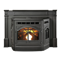
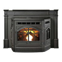
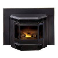
Castile & Santa Fe CE Insert
7069-101B
9
Appliance Set-Up
A. Leveling System
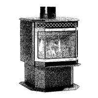
B. Outside Air Kit Instructions
Parts Included in Kit:1pieceof51mmx914mmex
hose,2hoseclamps,1collarassembly,1terminationcap
assembly,1trimring,fastenersandairintakechannel
(discard).
1. Measuredistancefromoortoairventopeninginappli-
anceandmarklocationonwall.
2. Usesawtocutopeninginwall.Cuta64to76mmopen-
ingoninsidewallanda76to89mmopeningonoutside
ofhouse.
3. Usehoseclamptosecureexpipetocollarassembly.
4. Slidetrimringoverexpipeandrunpipethroughwall.
5. Attach hose to outside termination cap with second
hoseclamp.
6. Secureterminationcaptooutsidesurface.
7. Securetrimringtointeriorwall.
Tools Needed:Phillipsheadscrewdriver;wirecutters;
holesaworjigsaw.
CAUTION
Neverdrawoutsidecombustionairfrom:
• Wall,oororceilingcavity
• Enclosedspacesuchasanatticorgarage
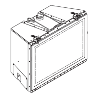
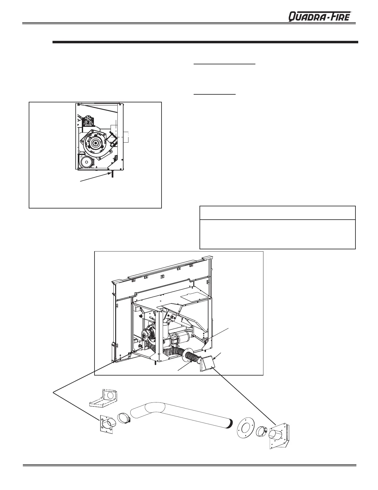
Thelevelingboltsarelocatedattherearoftheappliance.
Toaccessthebolts,removethesideaccesspanels.Reach
inandturnthebolttothedesiredheighttoleveltheappli-
ance.ShowninFigures 31.1 and 31.2.
Figure 31.1
Leveling Bolt on each Side
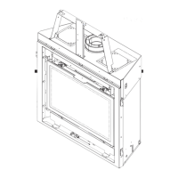
Flex Hose
Hose Clamp
Collar
Assembly
Hose Clamp
Trim Ring
Termination
Cap Assembly
Air Intake Channel (Discard)
Figure 31.2 (Shown on Castile Insert)
2 inch diameter Flex Pipe
Attach Termination
Cap to Exterior Wall
Leveling Bolt