Page32
October 27, 2011
R
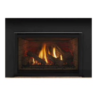
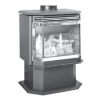
Castile & Santa Fe CE Insert
7069-101B
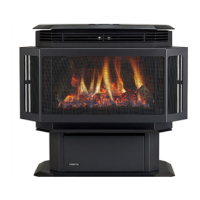
H. Surround and Cast Trim Set
(CASTILE INSERT)
Included in Surround Kit:(2)sidesurrounds,leftand
right;(1)surroundtop;(1)fastenerpackage.
Included in Cast Trim Kit:
(2)casttrimlegs,leftandright;(1)
casttrimheader;(2)casttrimfooters,leftandright
Tools Needed: Powered102mmto152mmPhillipshead
screwdriver
1. Removecontentsfromboxbeingcarefulnottoscratchor
damagethecasttrimpieces.
2. Lay the surround set face down on protective covering to
preventscratchingthepaintedsurface.
3. Usinga102mmto152mmlongPhillipsheadscrewdriverto
attachthesidesurroundstothetopsurroundusing(2)#8
sheetmetalscrewsoneachsideprovidedwiththekit.
4.
Placethepeelandstickroundfeltvibrationinsulationpadson
thefrontsideineachcornerofthetopmetalpieceandonthe
backsideineachcornerofthetopcastpiece.Figure 32.1.
5. Placethecorrespondingcasttrimpieces(2casttrimsides
and1casttrimheader)underneaththesurroundset,alsoface
down.Aligntheholesinthemetalpieceswiththe5bosses
onthetopcastpieceand2bossesoneachsidepiece.
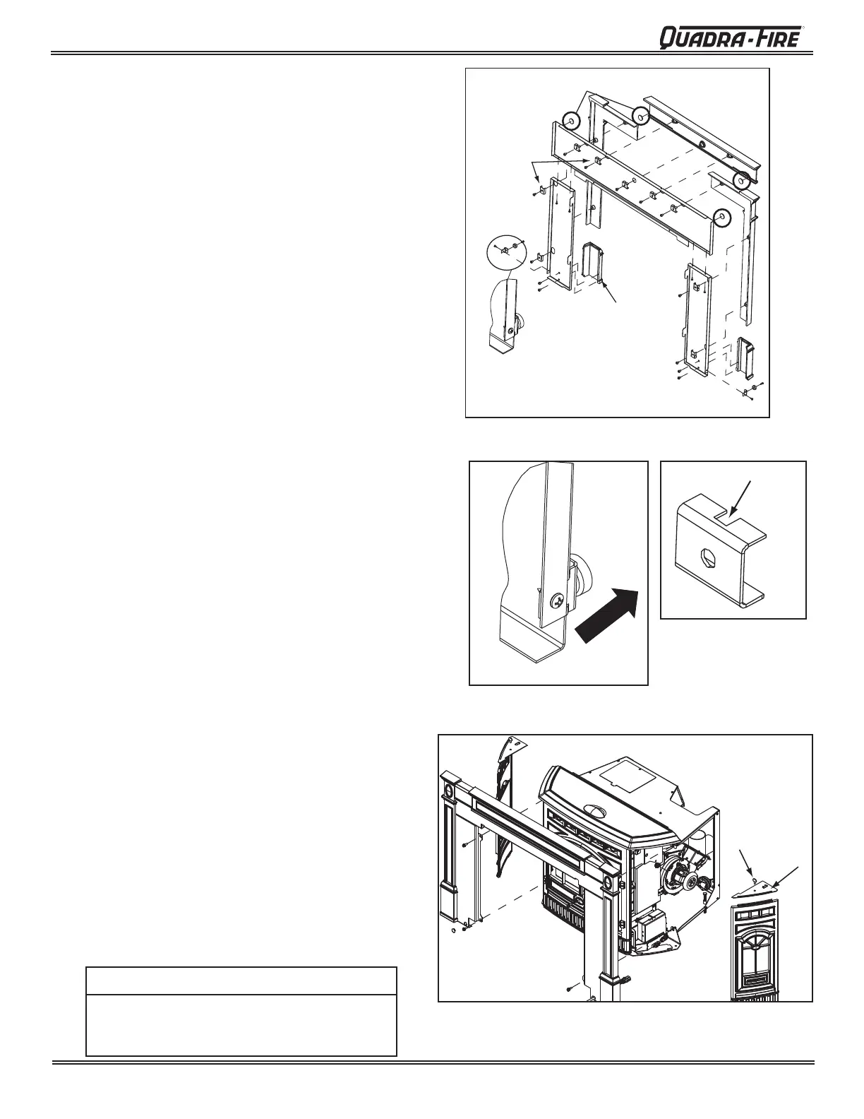
6. Securethemagnettothebracketandattachthemagnetand
brackettoeachmetalsidepieceatthebottom.Themagnet
isfacingthefront.Figure 32.2.
7. Placethecastfootersunderthemetalsidesaligningthetop
andbottomholesinthecastfootersandmetalsides.
8. The 9mountingclipsare shippedinonelongstrip.Hand
breakapartorusepliers.
9. Eachcliphasaclearancenotchtoallowroomforthecast
ontheinsert.Placetheclipsothenotchisfacingtheouter
edgesofthesurrounds.Figure 32.3.
10.Itisbesttoinstallallofthe1/4-20screwsonlyhalfwayat
rsttoallowforadjustments.Afteradjustment,tightenthe2
screwsineachcastfooterrstandthenworkyourwayaround
totherest.
11 Remove the cast sides before attaching the surround
andtrim.Liftupthetoptoexposethethumbscrewsat
thetopofcastside.Figure 32.4.
12.Remove the thumb screw and top bracket and then
removethecastside.Layitdownonasoftsurfaceto
avoidscratchingthecast.
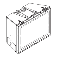
13 Slide surround and trim over the top of the insert into
place.Surroundattachstoinsertatthetopandbottom
ofinsertside.Figure 32.4.
14.Re-install the cast sides and secure with the thumb
screws.
Donotpickupassembledappliancebycorners.
Itistooheavyandmaydamagethesurrounds.
Pickupfromcenter.
CAUTION
(4) Felt Vibration Insulation Pads
Secure
Surrounds to
Cast Trim Kit
Attach Magnet
before installing
Cast Footers
Magnet Installed
Cast Footers,
Left & Right
Back
of
Side
Piece
Magnet Attached - Faces Front
Clearance Notch
Figure 32.2
Figure 32.3
Surround Set
attaches to top
and bottom of
insert sides.
Thumb
Screw
Figure 32.1
Figure 32.4