Interface Page 67 of 85
Section 3: Interface
3.1 Remote
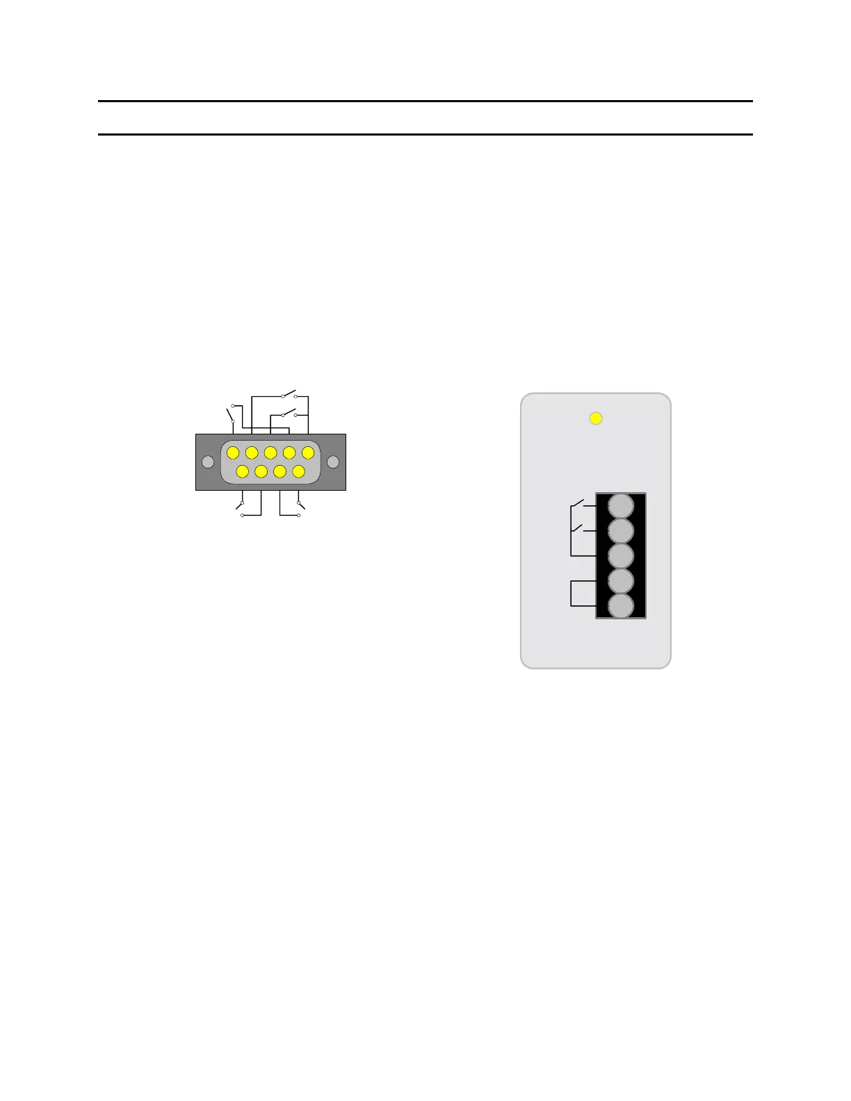
A 9-pin D-Series remote control connector is located on the rear panel of the Sentry Plus Series
instrument. There is a black 5 screw terminal strip for the remote input signals: START,
RESET, COM and INTERLOCK. Inputs require a contact closure. Figure 3-1 illustrates the
Remote terminal strip connector and 9-pin D-Series connector.
Before connecting the instrument to its power source, the interlock function on the rear panel
remote connector (terminal strip) must be properly utilized. This is an important safety feature
for the protection of the operator. When the INTERLOCK jumper is removed, there is no high
voltage at the OUTPUT. Therefore, to initiate a test make sure the interlock jumper is in place.
Figure 3-1: Sentry Plus Series Remote Connectors
The Sentry Plus Series instrument has three output signals on the rear panel. The UNDER TEST
relay is closed during a test. The PASS relay is closed when the DUT is judged GOOD. The
FAIL relay is closed when the DUT is judged NO GOOD. These relays are rated for voltage up
to 115VAC and current <100mA.
5-screw Remote Terminal Strip
9-pin D-Series Remote Connector
INTER
LOCK
COM
START
RESET
69
15
START
RESET
UNDER
TEST
FAILPASS