Page 22 of 85 Introduction
1.3 Controls and Indicators
1.3.1 Front Panel Controls and Indicators
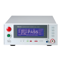
Figure 1-2 illustrates the controls and indicators on the front panel of the Sentry Plus Series
AC/DC/IR Hipot Tester. Table 1-1 identifies them with description and function.
1
3
2
8
6
7
54
11 10 9
F1
RTN/LOW
F2
OUTPUT
DANGERPASS FAIL
F1
F2
F3
F4
START
STOP
Sentry 30 Plus AC/DC/IR Hipot Tester
01
Q
uadTech
!
CAUTION
F4
F3
Max 5kVAC
6kVDC
CAL UPDATE
12
Figure 1-2: Sentry 30 Plus Front Panel Controls & Indicators
Table 1-1: Sentry 30 Plus Front Panel Controls & Indicators
Reference
Number
Figure 1-2
Name Type Function
1 Power Green Push Button Apply AC Power: 1=ON, 0=OFF
2 START Green Push Button Initiate Test: HV applied to OUTPUT terminal
3 STOP Red Push Button Stop Test: HV terminated at OUTPUT terminal
4 Display LCD Program Menu, Test Setup, Measurement Results,
Memory Contents, Calibration
5 F1, F2, F3
and F4
Gray Push Buttons Select Instrument Functions
Keys perform different functions under different menus.
Right side of display shows corresponding key function.
6 OUTPUT White Custom
Banana Socket
High Voltage (Potential) Terminal
7 RTN/LOW Blue Banana Socket RTN: Low voltage reference terminal
LOW: Common ground reference terminal
8 DANGER Red LED When lit, high voltage is present at OUTPUT terminals
9 FAIL Red LED When lit, DUT judged as FAIL. Output voltage is
immediately cut off. Press [STOP] to disable FAIL LED
10 PASS Green LED When lit, DUT judged as PASS
11 UPDATE Recessed P-B Qualified Service Personnel Only
12 CAL Recessed P-B Enable/Disable Instrument Calibration