QUANTECH
174
FORM QTC3-NM1
ISSUE DATE 08/03/2022
SECTION 9 – SERVICE AND TROUBLESHOOTING
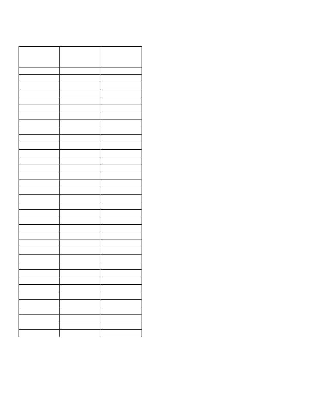
TABLE 32 - ENTERING/LEAVING CHILLED LIQ-
UID TEMP. SENSOR, TEMPERATURE/
VOLTAGE CORRELATION
TEMP °F
VOLTAGE
(SIGNAL INPUT
TO RETURN)
TEMP °C
10 1.33 -12
12 1.39 -11
14 1.46 -10
16 1.51 -9
18 1.58 -8
20 1.65 -7
22 1.71 -6
24 1.78 -4
26 1.85 -3
28 1.91 -2
30 1.98 -1
32 2.05 0
34 2.12 1
36 2.19 2
38 2.26 3
40 2.33 4
42 2.40 6
44 2.47 7
46 2.53 8
48 2.60 9
50 2.65 10
52 2.73 11
54 2.80 12
56 2.86 13
58 2.92 14
60 2.98 16
62 3.05 17
64 3.11 18
66 3.17 19
68 3.23 20
70 3.29 21
72 3.34 22
74 3.39 23
76 3.45 24
78 3.5 26
80 3.54 27
Liquid and Refrigerant Sensor Test Points
(See Table 32 on page 174)
Entering Chilled Liquid Sensor
J6-5 = +5 VDC regulated supply to sensor.
J6-8 = VDC input signal to the I/O board. See Table
32 on page 174 for voltage readings that cor-
respond to specific liquid temperatures.
J6-2 = drain (shield connection = 0VDC) Return
Leaving Chilled Liquid Temperature Sensor
J6-4 = +5 VDC regulated supply to sensor.
J6-7 = VDC input signal to the microboard. See Table
32 on page 174 for voltage readings that cor-
respond to specific liquid temperatures.
J6-1 = drain (shield connection = 0VDC) return
Analog Inputs – Pressure
See the unit wiring diagram. Pressure inputs are con-
nected to the microboard on plugs J7 and J9. These an-
alog inputs represent varying DC signals correspond-
ing to varying pressures. All voltages are in reference
to the unit case (ground).
System 1 discharge and suction pressures will be con-
nected to J7 of the microboard. System 2 discharge and
suction pressure transducers will be connected to J9 of
the microboard.
The discharge transducers are optional on all units. If
the discharge transducers are not installed, no connec-
tions are made to the microboard and the discharge
pressure readout on the display would be zero.
The suction pressure transducers are standard on all
QTC3’s. The suction pressure transducers have a range
of 0 psig to 400 psig. The output will be linear from 0.5
VDC to 4.5 VDC over the 400 psig (27.5 barg) range.
The discharge transducers have a range from 0 to 650
psig. The output will be linear from 0.5 VDC to 4.5
VDC over the 600 psig (41.25 barg) range. Following
is the formula that can be used to verify the voltage
output of the transducer. All voltage reading are in ref-
erence to ground (unit case).