Jive Up 19
Rev.2.0
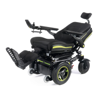
5.4 Drive wheel suspension Jive Up / QM-710 Stand
Up:
The
Jive Up / QM-710 Stand Up has an effective and
adjustable drive wheel suspension system as a standard
feature. To match your requirements on drive comfort, the
tension of the springs at the damper can be adjusted.
Turning the aluminium ring on the top of the spring
downwards will stiffen your ride, adjusting the aluminium
ring in a higher position will soften it. This option is to be
used to match the different user weights to the
suspension system. We recommend the suspension
adjustments are done equally on the left and right side of
the chair.
5.5 Control joystick unit position:
Depending on your chosen control system, there are two
principles of control systems: Quickie VR2 and Quickie R-
net controls (for details please see the controls section 7).
The remote is mounted on a sliding mechanism which
enables the control to be moved forwards and backwards.
• Undo the locking screw, (Fig.5.1, Previous).
• Slide the control arm either out or to it’s new position,
(Fig.5.2, Previous).
When the most comfortable position has been selected,
secure the slider by tightening the locking screw. Ensure
the locking screw is fully tightened prior to use and
especially when transporting your wheelchair.
5.6 Arm Rests:
5.6.1 Flip-Back Arm Rests:
The armrests on both sides of the wheelchair can be
flipped up to allow side transfer, (Fig. 5.5-5.6). For side
transfer flip the armrest all the way up until it goes into its
mechanical stop. This frees up space for side transfer.
To bring the armrests back into their position flip it all
the way down until it sits on its mechanical stop. Guide it
downward, do not let it fall on its own. (Fig. 5.7).
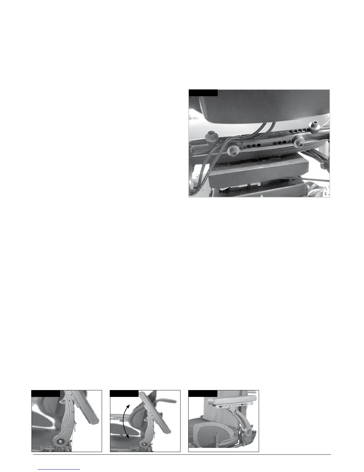
5.6.2 Adjusting the armrest width:
To adjust the width:
• Loosen the four screws (5mm allen key) on the
traversing tube as shown in (Fig. 5.8).
• Move the armrest receiver brackets to the desired
position.
• Tighten the screws firmly prior to use.
NOTE: Please check that the new arm rest position does
not interfere with any seat positioning.
Fig.5.7Fig.5.6
Fig.5.8
Fig.5.5