Jive Up / QM-710 Stand Up 37
Rev.2.0
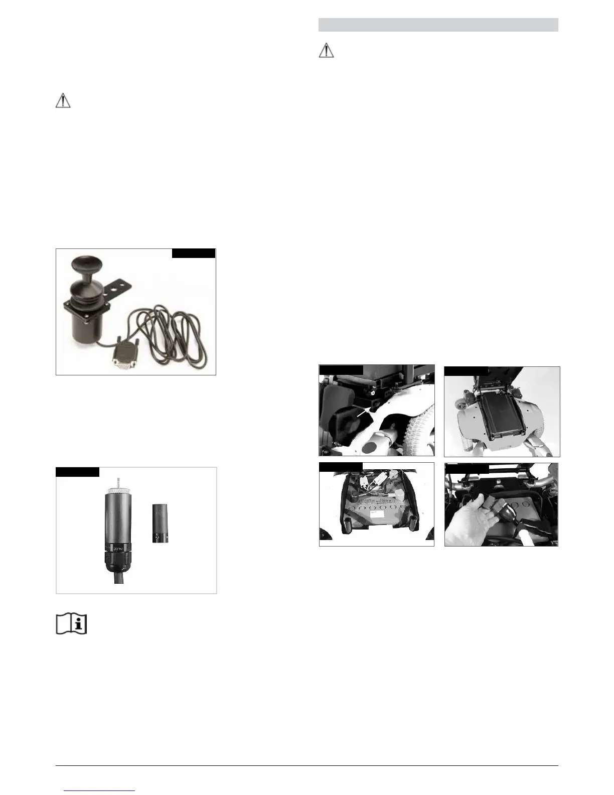
11.6 Proportional chin control (Fig.11.6)
The proportional chin control must be used in
conjunction with the Omni Plus module. This is to give
visual feedback for the selection of drive profiles and
seating options.
WARNING!
• Do not replace the joystick knob with any
unauthorised item. It may cause hazardous operation
and loss of control of the chair.
• It is important that the joystick boot is replaced if it is
torn or brittle; failing to do so could cause substance
damage to the controller and unexpected movement
of the chair.
• Ensure that you always have comfortable access to
the controls whilst the chair is moving and make sure
that the controller is fixed securely to the chair.
Fig. 11.6
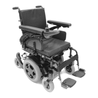
11.7 MicroPilot Joystick
The Micro Pilot joystick is a miniature joystick based
on a different technology than other mini “throw” based
joysticks. As little as 10 grams of force with virtually no
joystick deflection will activate the chair. All internal metal
construction means outstanding durability, (Fig 11.7).
Fig. 11.7
R-net, Omni Plus control
Please refer to the R-net Owner’s Manual for
details of R-net, Omni Plus control functions
12.0 Batteries and charging
WARNING!
• Please read the owner’s manual with the charger
supplied carefully. The general procedures and
effects for the interference with the chair and the
batteries remain valid.
• Do not expose any part of the battery to direct heat
(i.e. naked flame, gas fire).
• When charging always place your charger on a hard
surface in a room with good ventilation.
• You should not charge your batteries in outdoor
conditions.
12.1 Batteries
The batteries are contained within the drive unit located
under the battery shroud.
To remove the batteries first release the two handle
screws under the front of the seat frame, (Fig.12.1), which
connect the seat frame with the seat module interface.
Flip the seat frame backwards until the automatic lock
pin clicks to secure it in place, (Fig.12.2). Ensure the seat
is secure before letting go.
Lift off the battery box lid.
Disconnect the 2 pin Anderson connectors from each
battery (Fig.12.3 and 12.4).
There are straps available on each battery to facilitate
lifting them out. Remove the front battery first.
Fig. 12.1
Fig. 12.2
Fig. 12.3
Fig. 12.4