User’s Manual 31
3.7 Analog Reference Voltage Circuit
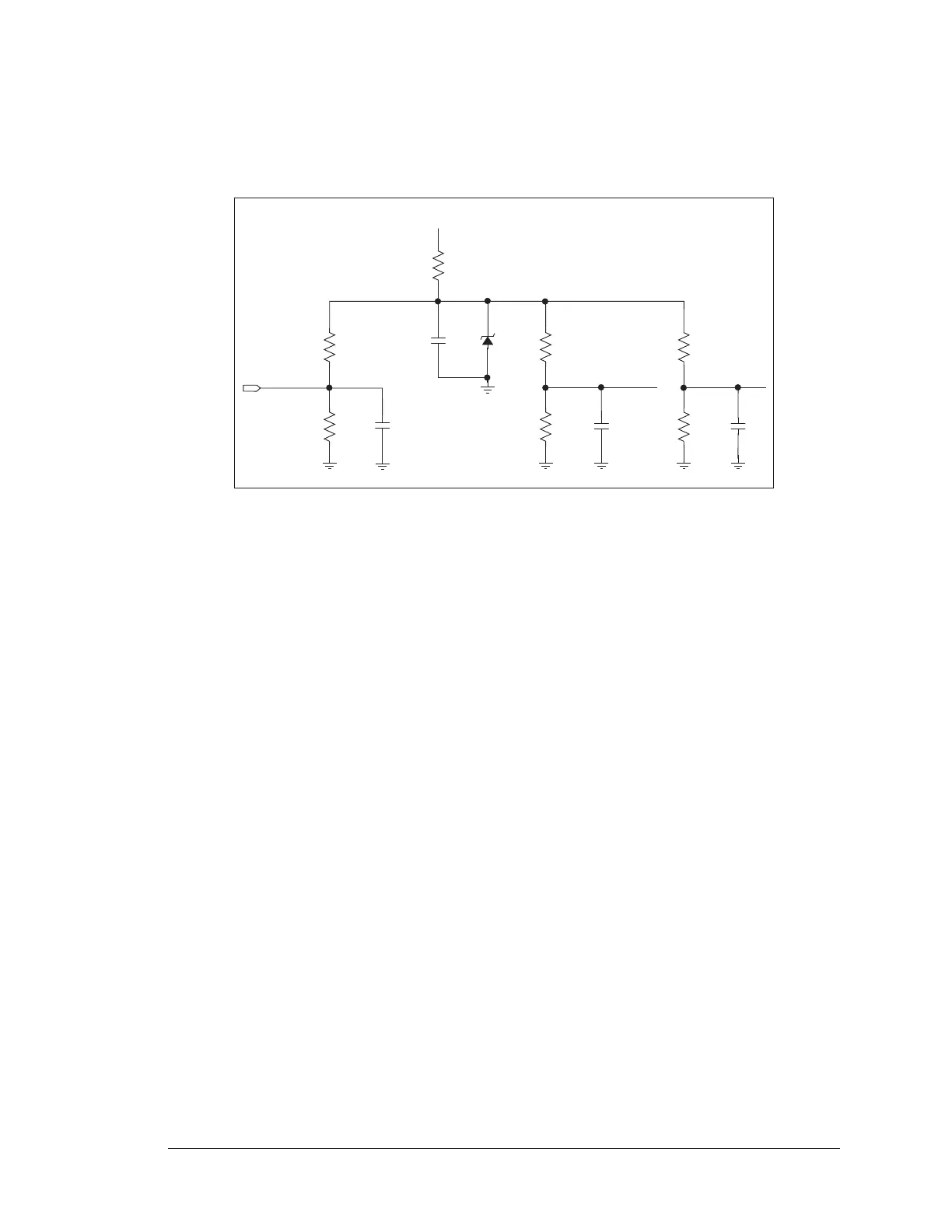
Figure 21 shows the analog voltage reference circuit.
Figure 21. Analog Reference Voltages
This circuit generates the 4.096 V reference voltage, which is used by the A/D converter
and by the D/A converters. This sets the operating range of the A/D converter and the D/A
converters (0–10 V). To use the full accuracy of the A/D converter and the D/A convert-
ers, this voltage must be accurate to the same degree.
The reference zener diode in combination with the 300 resistor form a shunt regulator.
The 4.096 V reference voltage then feeds the A/D converter, the D/A converters, and the
voltage divider composed of the 10 k and the 14 k resistors. The voltage divider gener-
ates a second reference voltage of 1.707 V to feed the four op-amps for the buffered A/D
converter inputs.
The 2.048 V reference voltage is also used to generate the 2.5 V reference for D-REF used
in the digital output circuit.
10 kW
ADREF
14 kW
100 nF
100 nF
300 W
+V
4.096 V
4.096 V
ref diode
100 nF
25.5 kW
25.5 kW
2.048 V
100 nF
10.2 kW
25.5 kW
1.707 V
2.926 V