User’s Manual 83
C.4 Header Pinouts
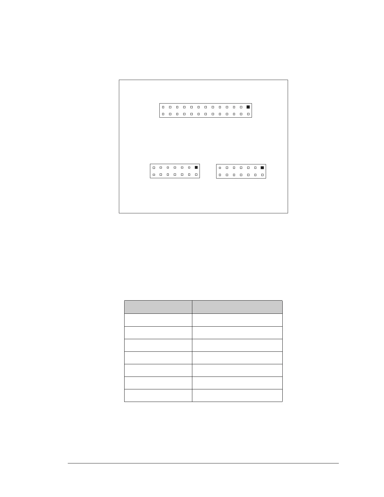
Figure C-6 shows the pinouts for the LCD/keypad module.
Figure C-6. LCD/Keypad Module Pinouts
C.4.1 I/O Address Assignments
The LCD and keypad on the LCD/keypad module are addressed by the PE7 strobe as
explained in Table C-2.
Table C-2. LCD/Keypad Module Address Assignment
Address Function
Exx0–Exx7 LCD control
Exx8 LED enable
Exx9 Not used
ExxA 7-key keypad
ExxB (bits 0–6) 7-LED driver
ExxB (bit 7) LCD backlight on/off
ExxC–ExxF Not used
DB6B
DB4B
DB2B
DB0B
A1B
A3B
GND
LED7
LED5
LED3
LED1
/RES
VCC
DB7B
DB5B
DB3B
DB1B
A0B
A2B
GND
GND
LED6
LED4
LED2
PE7
+5BKLT
J1
GND
GND
LED6
LED4
LED2
PE7
+5BKLT
GND
LED7
LED5
LED3
LED1
/RES
VCC
J2
GND
DB7B
DB5B
DB3B
DB1B
A0B
A2B
GND
DB6B
DB4B
DB2B
DB0B
A1B
A3B
J3