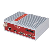
4.2. Connectors
All connectors are located on the front panel. The upper side features an LED panel. The RESET button
is located in an opening in the bottom side.
HW ALARMOUTPUT
HW ALARMINPUT
+ –
SLEEP INPUT
COM1
COM2
ETH
MANAGEMENT
WiFi ADAPTER
ETH/USB ADAPTER
ANTENNA
10–30VDC
+
+
ETH
Fig. 4.5: Connectors
Warning – hazardous locations
Do not manipulate the RipEX (e.g. plug or unplug connectors) unless powered down or the
area is known to be non-hazardous.
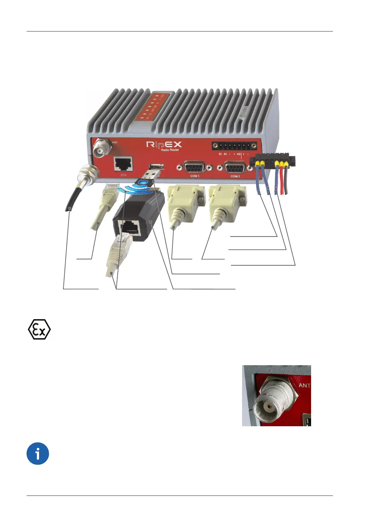
4.2.1. Antenna
Fig. 4.6: Antenna connector TNC
An antenna can connect to RipEX via TNC female 50Ω connector.
A model with two antenna connectors can be supplied to order,
in which the Rx and Tx antennas are separate. This model is
typically used on communication towers where one Rx and one
Tx antennas are common for most devices.
See chapter Section 4.5, “Model offerings”.
Note
Frequency split (different Rx and Tx frequency) is independent from the presence of two
antenna connectors. It can be set even on standard RipEX with one antenna connector.
RipEX Radio modem & Router – © RACOM s.r.o.46
Product