If the external device requires connection to positive terminal of
the power supply, PIN 4 should be used.
POWER
The POWER pins labelled + and - serve to connect a power supply 10–30 VDC. The requirements for
a power supply are defined in Section 6.6, “Power supply” and Section 4.4, “Technical specification”.
4.2.3. ETH
Standard RJ45 connector for Ethernet connection. RipEX has 10/100 BaseT Auto MDI/MDIX interface
so it can connect to 10 Mbps or 100 Mbps Ethernet network. The speed can be selected manually or
recognised automatically by RipEX. RipEX is provided with Auto MDI/MDIX function which allows it to
connect over both standard and cross cables, adapting itself automatically.
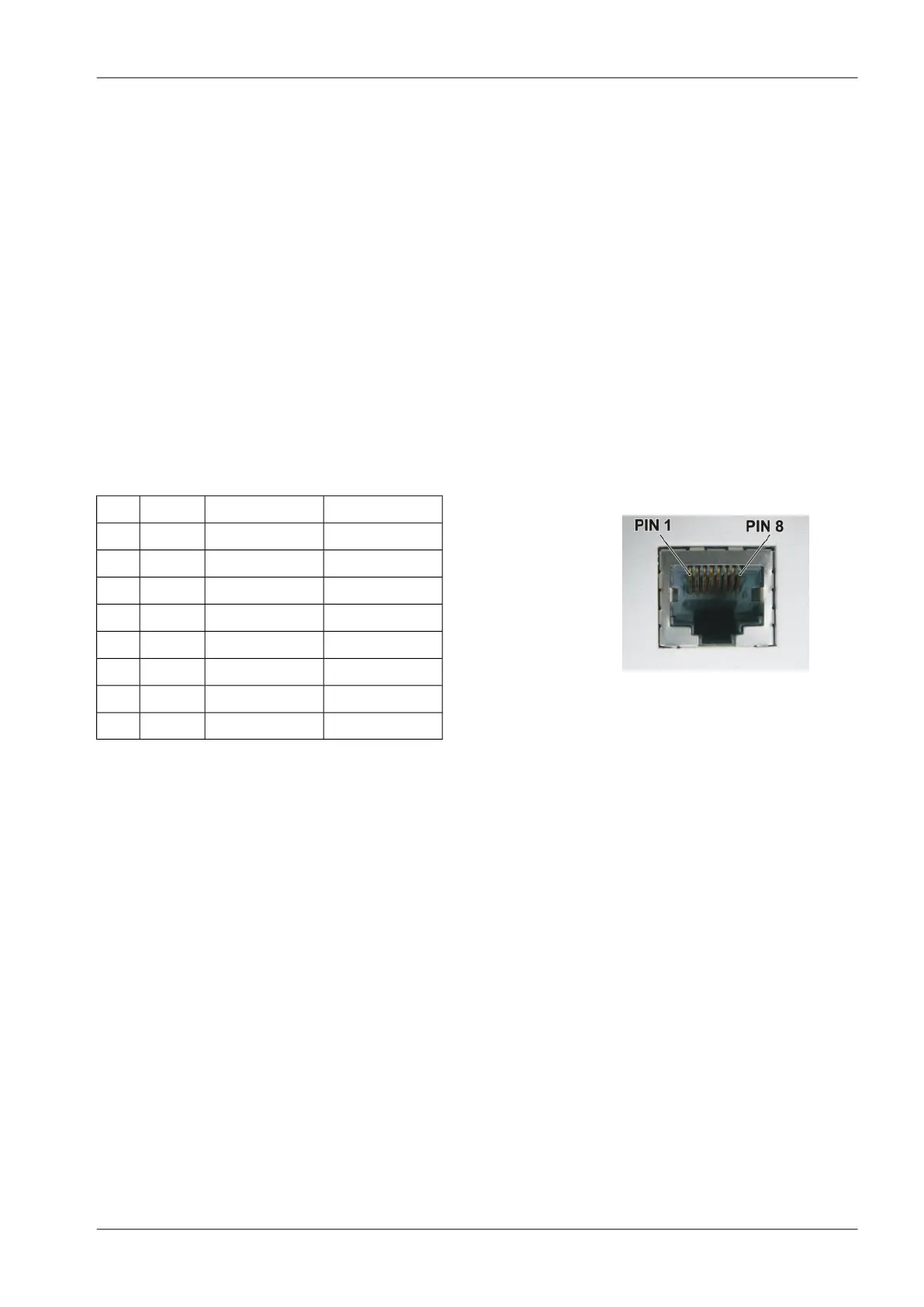
Pin assignment
Fig. 4.10: RJ-45F
Tab. 4.2: Ethernet to cable connector connections
Crossed cableDirect cableSignalPIN
green – whiteorange – whiteTX+1
greenorangeTX−2
orange – whitegreen – whiteRX+3
blueblue—4
blue – whiteblue – white—5
orangegreenRx−6
brown – whitebrown – white—7
brownbrown—8
4.2.4. COM1 and COM2
RipEX provides two serial interfaces COM1 and COM2 terminated by DSUB9F connectors. COM1 is
always RS232, COM2 can be configured as RS232 or RS485 (more in Adv. Conf., COM).
RipEX‘s RS232 is a hard-wired DCE (Data Communication Equipment) device. Equipment connected
to the RipEX’s serial ports should be DTE (Data Terminal Equipment) and a straight-through cable
should be used. If a DCE device is connected to the RipEX‘s serial ports, a null modem adapter or
cross cable has to be used.
49© RACOM s.r.o. – RipEX Radio modem & Router
Product