Warning – hazardous locations
Antenna has to be installed outside of the hazardous zone.
Fig. 4.7: Separated Rx and Tx antennas
Warning: RipEX radio modem may be damaged when operated without an antenna or a dummy load.
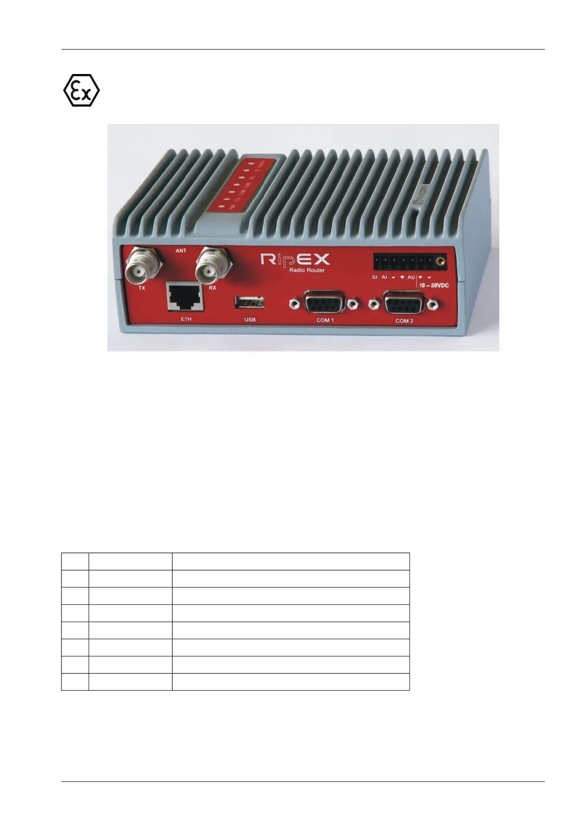
4.2.2. Power and Control
This rugged connector connects to a power supply and it contains control signals. A Plug with screw-
terminals and retaining screws for power and control connector is supplied with each RipEX. It is Tyco
7 pin terminal block plug, part No. 1776192-7, contact pitch 3.81 mm. The connector is designed for
electric wires with a cross section of 0.5 to 1.5 mm
2
. Strip the wire leads to 6 mm (1/4 inch). Isolated
cables should receive PKC 108 or less end sleeves before they are inserted in the clip. Insert the cables
in the wire ports, tightening securely.
Tab. 4.1: Pin assignment
signallabeledpin
SLEEP INPUTSI1
HW ALARM INPUTAI2
−(GND) – for SLEEP IN, HW ALARM INPUT−3
+(POWER) – for HW ALARM OUTPUT+4
HW ALARM OUTPUTAO5
+POWER (10 to 30 V)+10–30VDC6
−POWER (GND)−10–30VDC7
Pins 3 and 7, 4 and 6 are connected internally.
47© RACOM s.r.o. – RipEX Radio modem & Router
Product