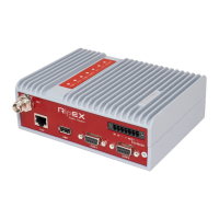
Warning – hazardous locations
The unit must be powered with an intrinsic save power source for use in hazardous locations.
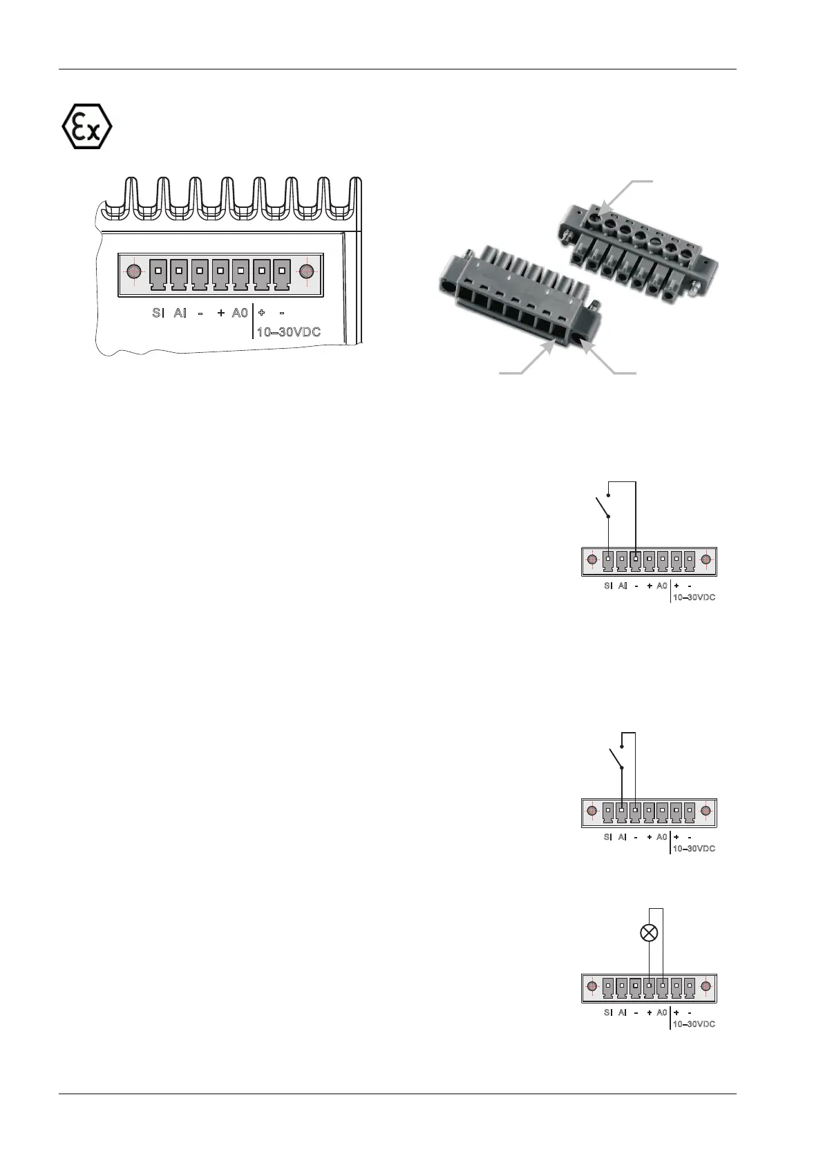
1 2 3 4 5 6PinNo.: 7
SI AI - + A0
+
-
10–30VDC
Fig. 4.8: Supply connector
Wire
Ports(7)
Retaining
Screws(2)
Lead
Binding
Screws(7)
Fig. 4.9: Power and Control - cable plug
1 2 3 4 5 6PinNo.: 7
SI AI - + A0
+
-
10–30VDC
SleepInput
SLEEP INPUT
SLEEP INPUT is the digital input for activating the Sleep mode.
When this pin is grounded (for example when connected to pin
3), the RipEX switches into the Sleep mode. Using Power man-
agement (Advanced Config.), the Entering the Sleep mode can
be delayed by a set time. Disconnecting SLEEP INPUT from
GND (-) ends the Sleep mode. Note that RipEX takes 48 seconds
to wake up from the Sleep mode.
SLEEP INPUT can be also used for the wake-up from the Save
state. For details see chapter (Advanced Config., Power manage-
ment)
1 2 3 4 5 6PinNo.: 7
SI AI - + A0
+
-
10–30VDC
AlarmInput
HW ALARM INPUT
HW ALARM INPUT is a digital input. If grounded (e.g. by connect-
ing to PIN 3), an external alarm is triggered. This alarm can be
used for example to transmit information using SNMP trap, in-
forming for instance about a power outage or RTU problem. For
details about Alarm management see chapter Advanced Config-
uration.
1 2 3 4 5 6PinNo.: 7
SI AI - + A0
+
-
10–30VDC
AlarmOutput
max.30VDC,1 A
HW ALARM OUTPUT
HW ALARM OUTPUT is a digital output. It can be activated
in Alarm management settings, chapter Advanced Configuration.
It may be used for instance to inform the connected RTU about
a RipEX alarm or about the Unit ready status. If an alarm is
triggered, HW ALARM OUTPUT is internally connected to GND.
RipEX Radio modem & Router – © RACOM s.r.o.48
Product